AP10S
Installation English
AP10S · Date 15.04.2020 · Art. No. 87100 · Mod. status 83/20
29
24 V
24 V
CAN_GND
CANL
CANH
120 R
CANH
CANL
Node 1
120 R
Node n
0 V
0 V
Bus-Master
Versorgung
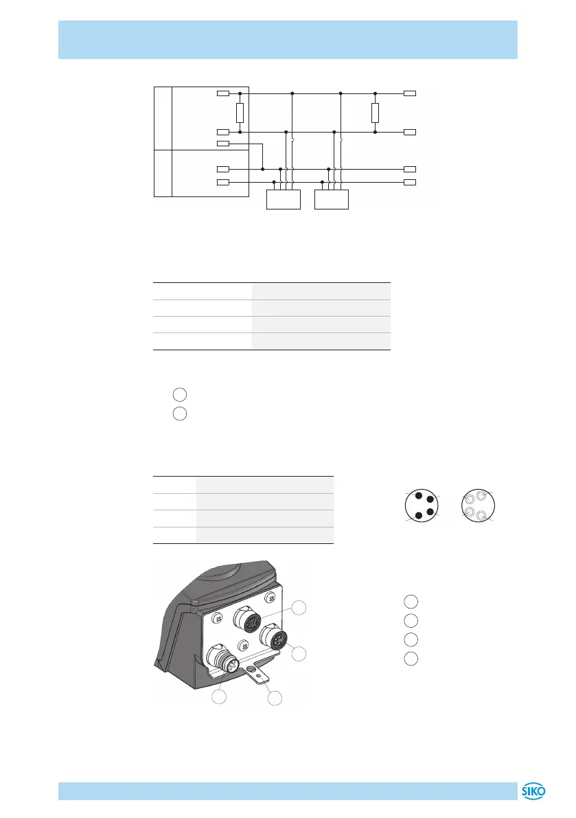
Fig. 3: Connection diagram CAN
Data transfer CAN interface
CAN baud rate max. bus network length
125kbit/s 320m
250bit/s 160m
500bit/s 80m
1Mbit/s 25m
Pin assignment
•
1
Bus-IN: Pin 4 pin M8 (see Fig. 4).
•
2
Bus-OUT: Female 4 pin M8 (see Fig. 4).
For mating connector and cable extension accessories see chapter 8.
PIN Designation
1 DÜB/CANL
2 DÜA/CANH
3 +UB
4 GND
1
Bus-IN
2
Bus-OUT
3
Sensor
4
Ground connection
Fig. 4: Pin assignment
Strand cross sections of lines 0.14 ... 0.5mm².
viewing side = plug-in side
Bus-OUTBus-IN
 Loading...