AP10S
Installation English
AP10S · Date 15.04.2020 · Art. No. 87100 · Mod. status 83/20
28
Connect the sensor
3
to the AP10S via the 6-pin jack (see Fig. 4 + chap-
ter 5.1).
Connection diagram
Faulty or missing termination
Faulty or missing termination or level specification results in communica-
tion errors and can destroy the displays electronic system.
` Make sure that termination is correct and test it.
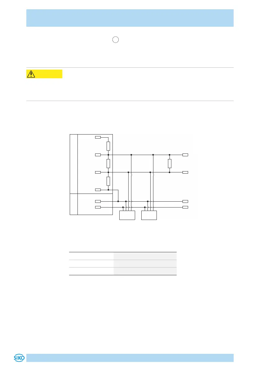
Connection diagram and level specification RS485
If termination and level specification do not occur in the bus master, they
must be carried out externally.
Node n
SGND
RS485-
RS485+
120 R
DÜA
DÜB
120 R
+5 V
470 R
470 R
0 V
24 V
24 V
0 V
Node 1
Bus-MasterVersorgung
Fig. 2: Connection diagram and level specification RS485
Data transfer RS485 interface
RS485 baud rate max. bus network length
115.2kbit/s 200m
57.6kbit/s 400m
19.2kbit/s 1200m
Connection diagram CAN
A terminating resistor (120Ohm) is required for the fieldbus function,
which must be included at the last bus subscriber between CANH and
CANL.
CAUTION
 Loading...