beside VBAT_RF pins as close as possible. Also User should minimize the PCB trace impedance from the
power supply to the VBAT pins through widening the trace to 80 mil or more on the board. The following
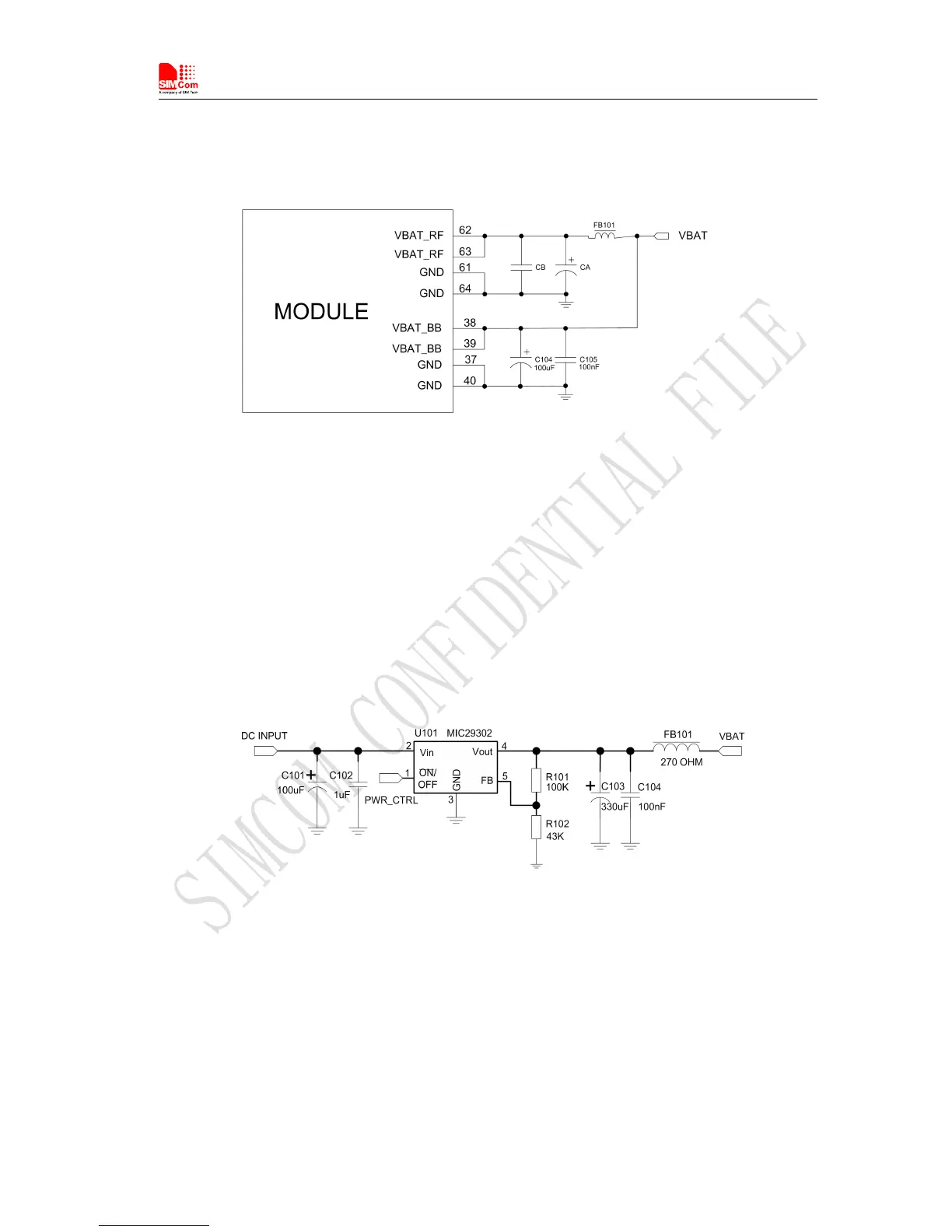
figure is the recommended circuit.
Figure 8: VBAT input application circuit
There are three sections about how to design and optimize users’ power systems.
Power supply circuit
We recommend DCDC or LDO is used for the power supply of the module, make sure that the peak
current of power components can rise up to more than 2A. The following figure is the reference design of
+5V input power supply. The designed output for the power supply is 4.1V, here a linear regulator can be
used.
Figure 9: Reference circuit of the LDO power supply
If there is a big difference between the input voltage and the desired output (VBAT), a switching converter
power will be preferable because of its better efficiency, especially at the high current situation. The
following figure is the reference circuit. Note that DCDC may deprave RF performance because of ripple
current intrinsically.