Note: If more GPIOs need to be used, users can configure GPIO on other multiple function interfaces, such as KEYPAD.
Please refer to GPIO list.
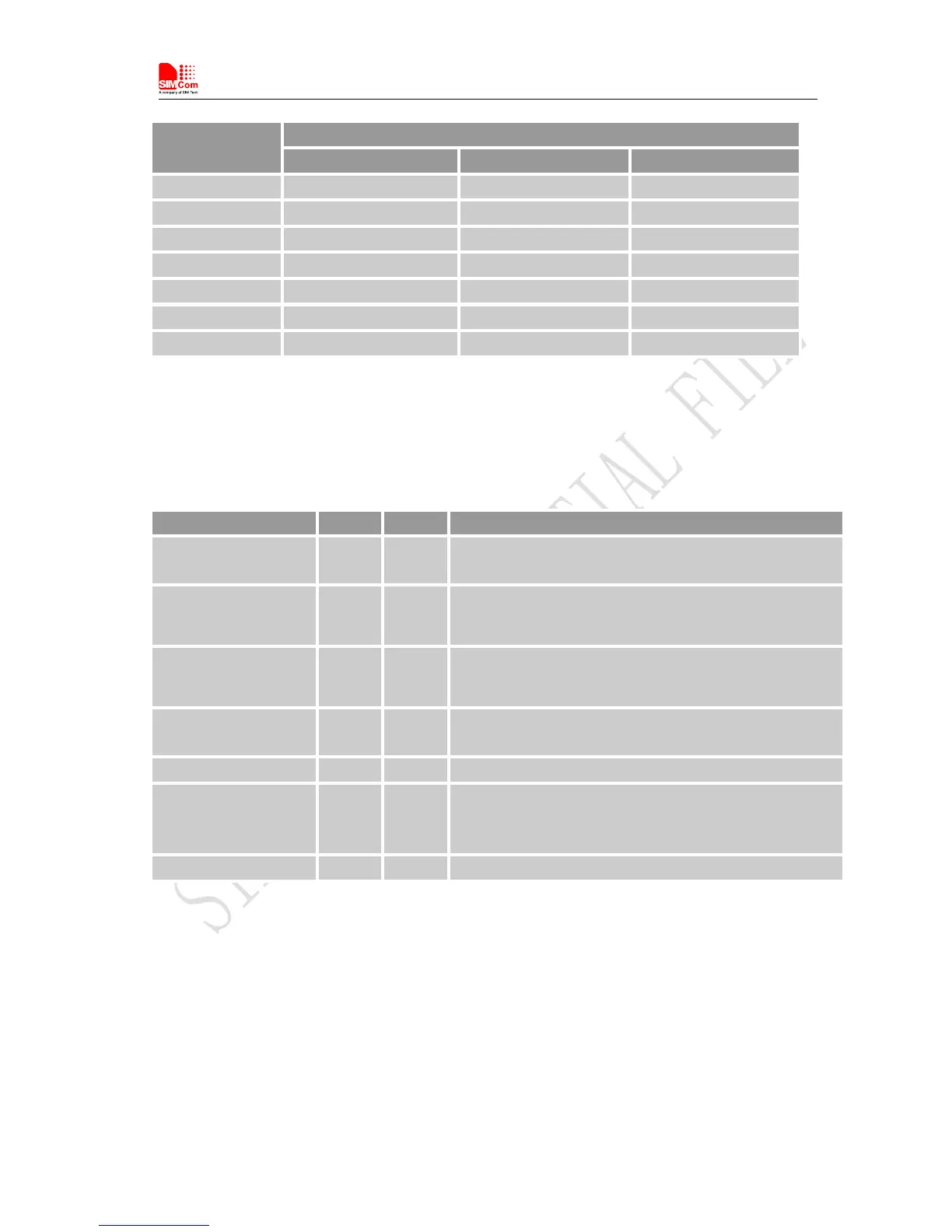
Table 24: Pin description
Note: The output driver current of GPIOs is 1mA at the lower supply voltage and 2mA at the higher supply voltage.
Pin name Pin No. I/O Function
GPIO1 51 O
Output PIN as LED control for network status. If it is
unused, left open.
GPIO4 54 I
Input PIN as RF operating control.
H: Normal Mode L:Flight Mode
If it is unused, left open.
GPIO40 49 O
Output PIN as operating status indicating of module.
H: Power on L: Power off
If it is unused, left open.
GPIO41 52 I/O
General input/output PIN. It can be used as wake/interrupt
signal to host from module If it is unused, left open.
GPIO42 53 I/O General Purpose Input/Output Port.
GPIO43 50 I/O
General Purpose Input/Output Port. It can be used as
wake/interrupt signal to module from host. If it is unused, left
open.
GPIO44 48 I/O General Purpose Input/Output Port