PCM_DIN/GPIO0 74 AUX_PCM_DIN PCM_DIN PCM data input
PCM_SYNC/GPIO2 75 AUX_PCM_SYNC PCM_SYNC PCM data synchrony
PCM_DOUT/GPIO5 73 AUX_PCM_DOUT PCM_DOUT PCM data output
PCM_CLK/GPIO3 76 AUX_PCM_CLK PCM_CLK PCM data clock
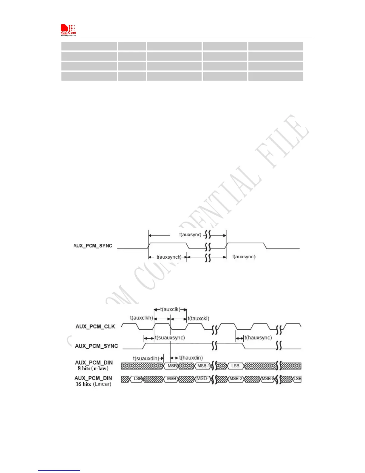
The default PCM interface in SIM5320 is the auxiliary PCM interface. The data changes on the high level
of PCM_CLK and is sampled at the falling edge of PCM_CLK in one period. Primary PCM is disabled
after every power-on or every reset event. So user must use AT command to enable the primary PCM
mode after powering on or resetting the module every time if user wants to use Primary PCM.SIM5320
PCM Interface can be operated in Master or Slave mode if it is configured to primary PCM. In Master
Mode, the Module drives the clock and sync signals that are sent to the external codec. When it is in Slave
Mode, the external codec drives the clock and sync signals which are sent to the module. Both PCM
modes are discussed in this section followed by additional PCM topics.
Auxiliary PCM (128 KHz PCM clock)
-law coding is supported by the auxiliary PCM. The auxiliary codec port operates with standard
long-sync timing and a 128 KHz clock. The AUX_PCM_SYNC runs at 8 KHz with 50% duty cycle.
Most
-law codec support the 128 KHz clock.