All keypad pins can be configured for GPIOs. These GPIOs also support interruption operation if used as
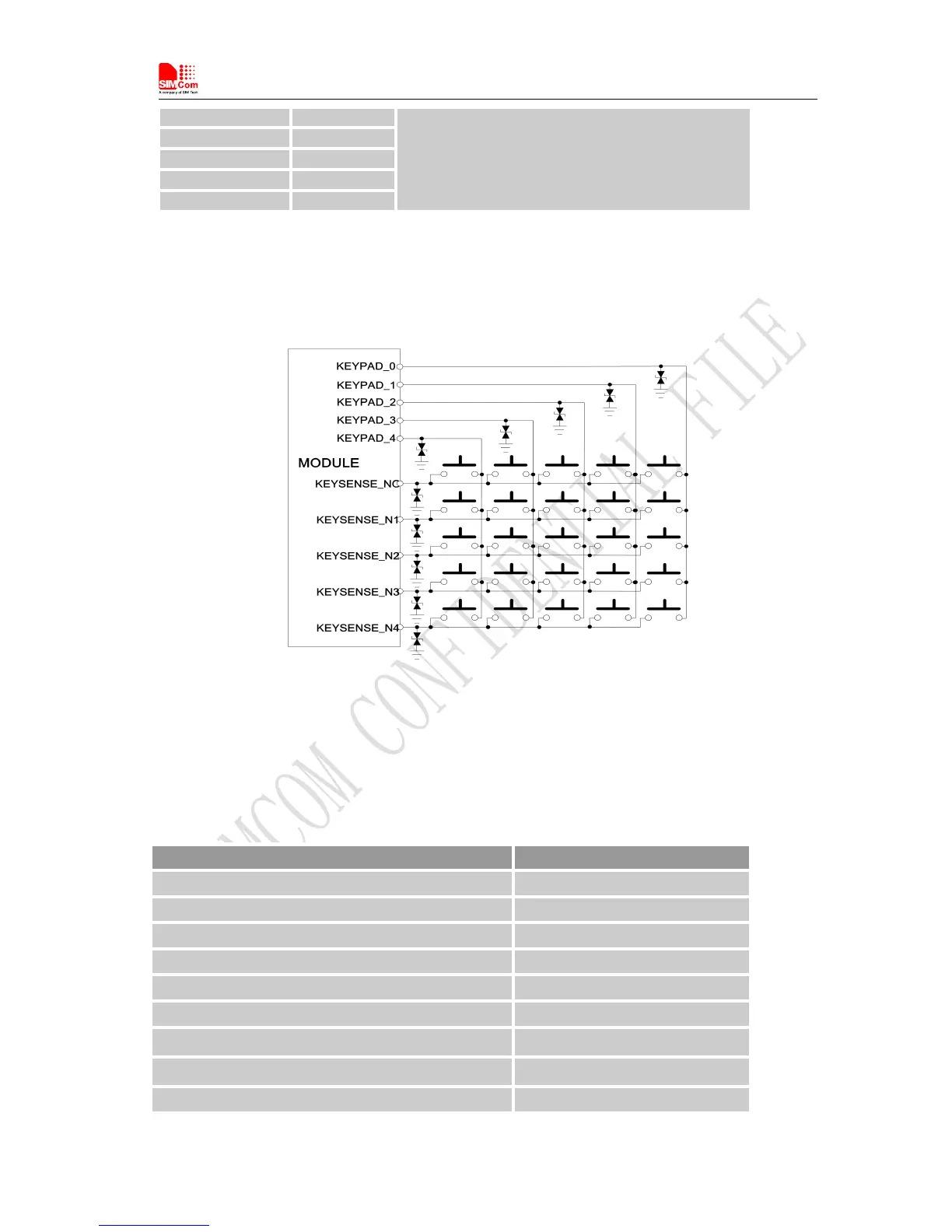
input pins. A typical circuit about the keypad (5*5 keypad matrix) is shown in the following figure.
Figure 26: Reference circuit
If these pins are configured for GPIOs, the sequence is listed in the following table.
Table 19: GPIO configuration
Keypad interface GPIO No.
KEYPAD_4 GPIO6
KEYPAD_3 GPIO7
KEYPAD_2 GPIO8
KEYPAD_1 GPIO9
KEYPAD_0 GPIO10
KEYSENSE_N4 GPIO11
KEYSENSE_N 3 GPIO12
KEYSENSE_N 2 GPIO13
KEYSENSE_N 1 GPIO14