Smart Machine Smart Decision
SIM5320AL_User Manual_V1.01 2014-08-20
Note: The sinking current can be adjusted to meet design requirement through the AT command “AT+ CLEDITST =<0>,
<value>”.The “value” ranges from 0 to 15,on behalf of the current changes from 0mA to 150mA in steps of 10mA.
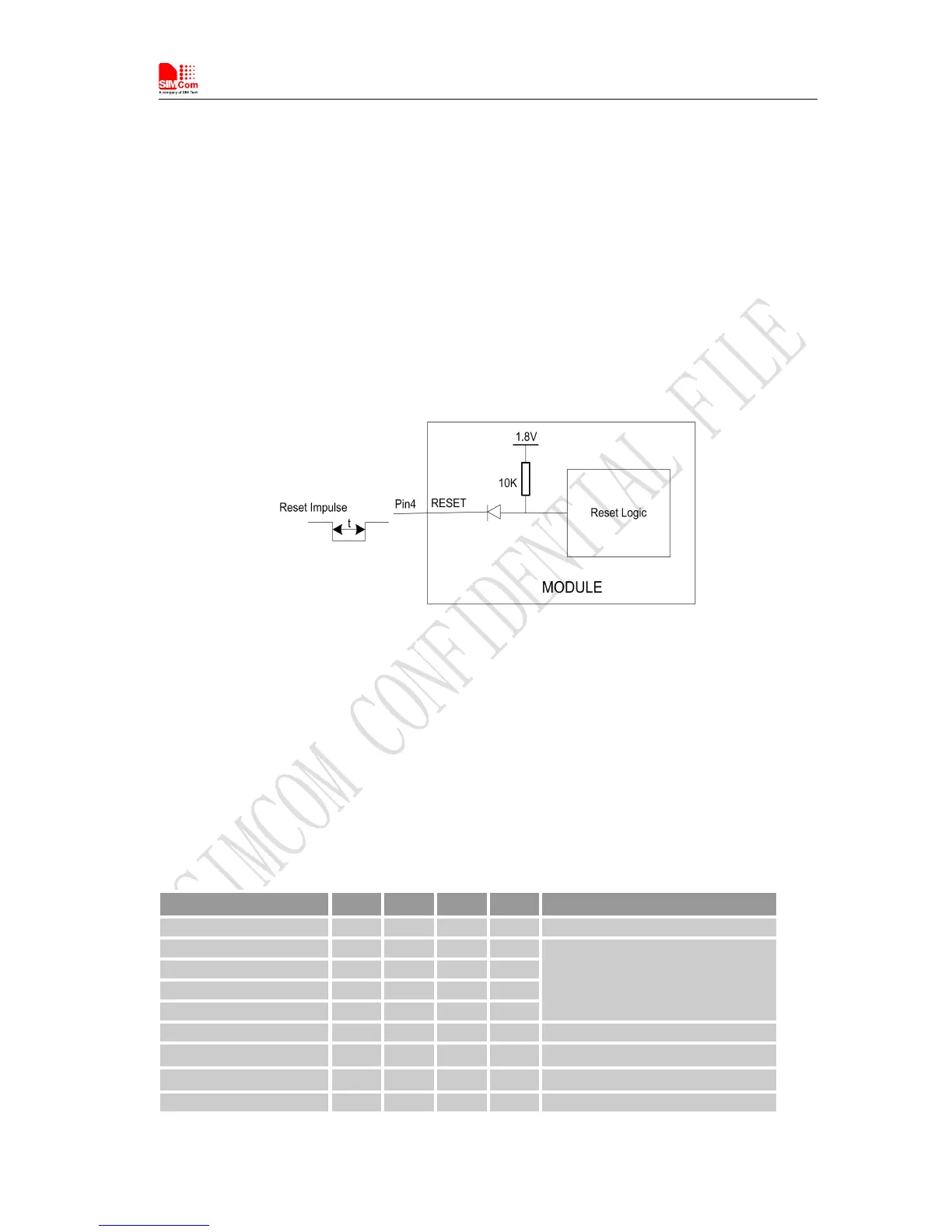
SIM5320AL also have a RESET pin (PIN4) to reset the module. This function is used as an emergency
reset only when AT command “AT+CPOF” and the POWER_ON pin has no effect. User can pull the
RESET pin to ground, then the module will reset.
This pin is already pulled up in module, so the external pull-up resistor is not necessary. A 100nF capacitor
close to the RESET pin is strongly recommended. A reference circuit is recommended in the following
figure.
Figure 37: Reset circuit
Note
:
50ms<t<200ms. ESD components are suggested to be used on Reset pin.
SIM5320AL has a dedicated ADC that is available for digitizing analog signals such as battery voltage and
so on; it is on PIN 47 and PIN 46 , namely ADC1 and ADC2 . This ADC is 12 bit
successive-approximation circuit, and electronic specification is shown in the following table.
Table 32: Electronic Characteristics
Specification Min Typ Max Unit Comments/Conditions
Resolution 12 Bits
Differential nonlinearity -4 +4 LSB
Analog Vdd = ADC reference
2.4MHz sample rate
Integral nonlinearity -8 +8 LSB
Gain Error -2.5 +2.5 %
Offset Error -4 +40 LSB
Input Range GND 2.2V V
Input serial resistance 2 kΩ Sample and hold switch resistance
Input capacitance 53 pF
Power-down to wakeup 9.6 19.2 μs