Smart Machine Smart Decision
SIM7600V-H_User Manual_V1.00 2018-02-24
On VBAT pads, a ripple current up to 2A typically, may cause voltage drop. Therefore, the power
supply for these pads must be able to provide sufficient current up to more than 2A in order to
avoid the voltage drop of more than 300mV.
Table 6: VBAT Pins electronic characteristic
Module power peak current in normal mode.
Module power average current in normal mode
Please refer to the table 34
Power supply current in sleep mode
Module power current in power off mode.
3.1.1 Power supply Design Guide
Make sure that the voltage on the VBAT pins will never drop below 3.4V.
Note: If the power supply for BAT pins can support up to 2A, using a total of more than 220uF
capacitors is recommended, or else users must use a total of 1000uF capacitors, in order to avoid
the voltage drop of more than 300mV.
Some multi-layer ceramic chip (MLCC) capacitors (0.1/1uF) with low ESR in high frequency band
can be used for EMC.
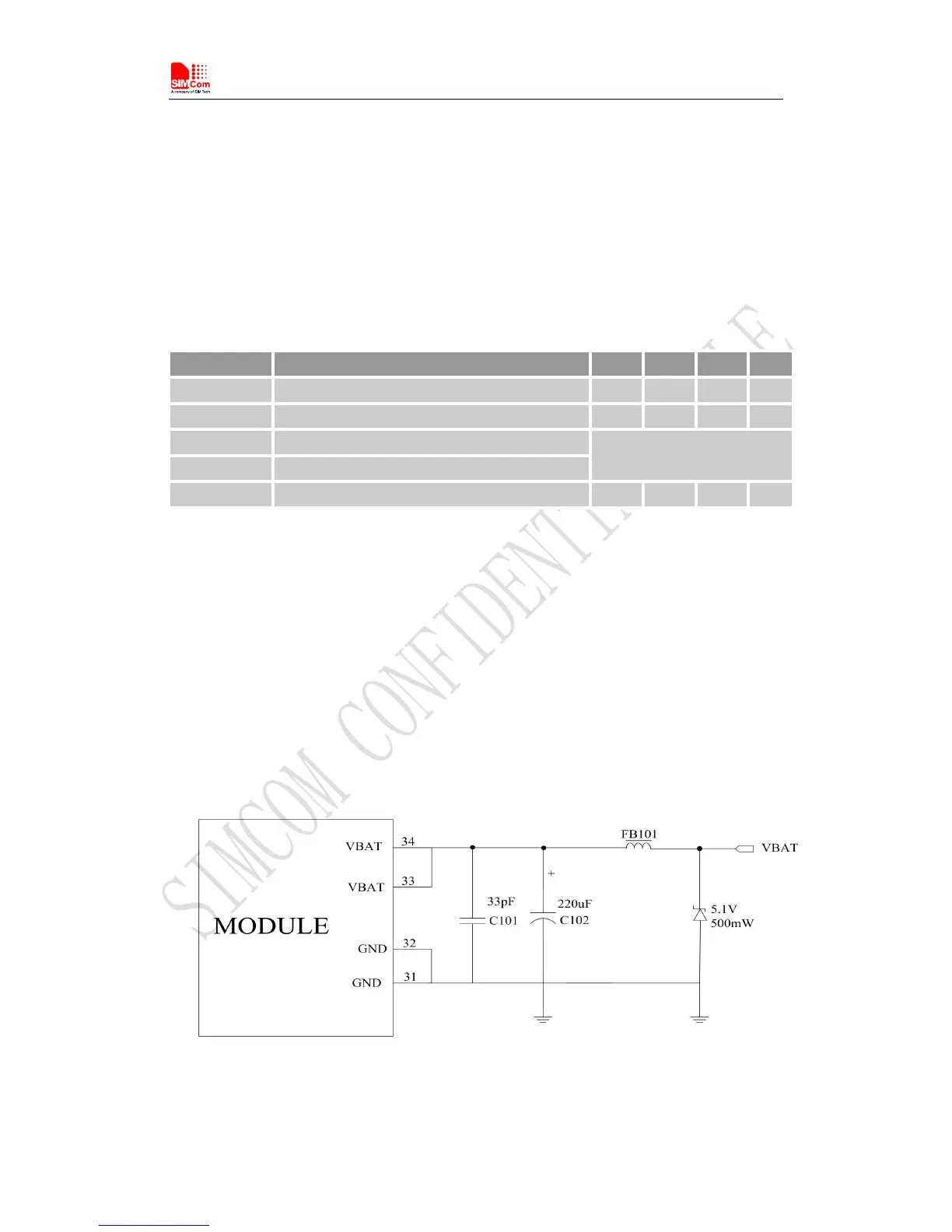
These capacitors should be put as close as possible to VBAT pads. Also, user should keep VBAT
trace on the circuit board wider than 2 mm to minimize PCB trace impedance. The following figure
shows the recommended circuit.
Figure 5: Power supply application circuit