EasyManuals Logo

SimCom SIM7600V-H User Manual

SimCom SIM7600V-H
60 pages
To Next Page IconTo Next Page
To Previous Page IconTo Previous Page
Page #25 background imageLoading...
Page #25 background image
Smart Machine Smart Decision
SIM7600V-H_User Manual_V1.00 2018-02-24
25
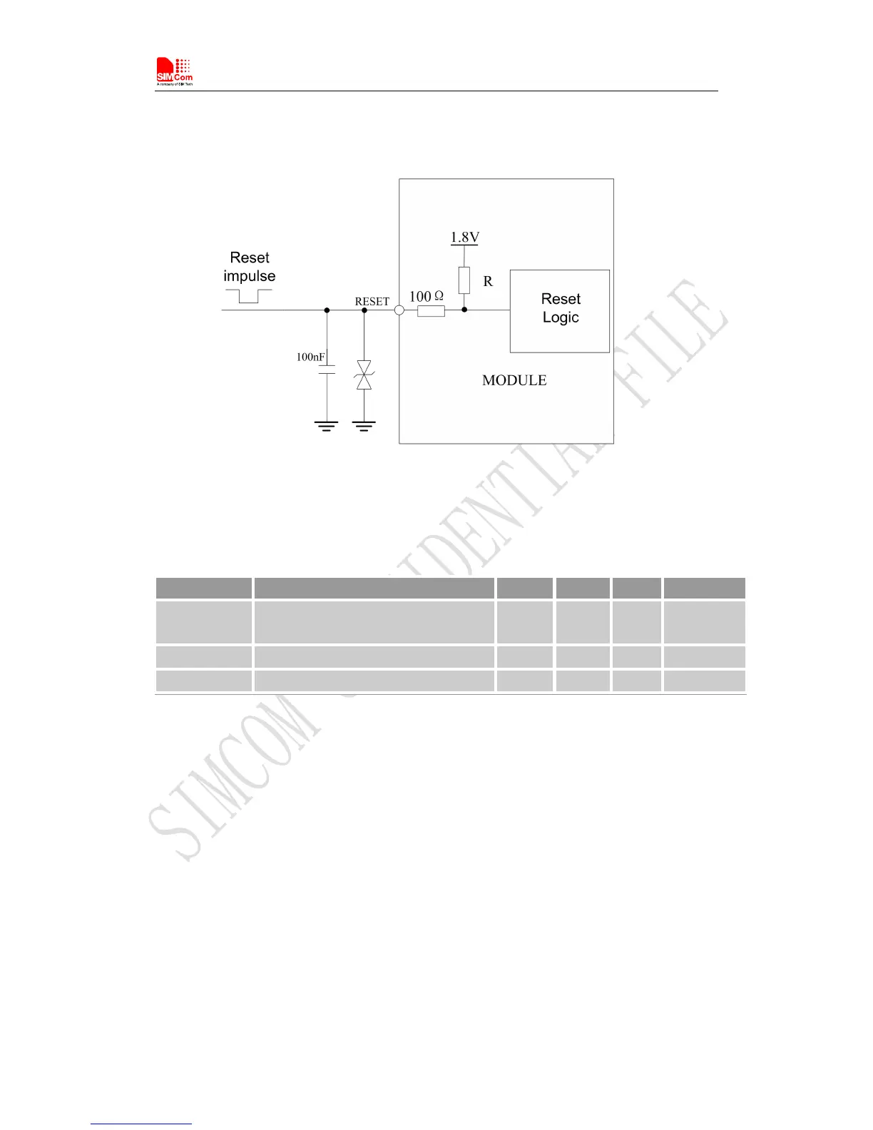
The RESET pin has been pulled up to 1.8V internally, so it does not need to be pulled up externally.
It is strongly recommended to put a100nF capacitor and an ESD protection diode close to the
RESET pin. Please refer to the following figure for the recommended reference circuit.
Figure 11: Reference reset circuit
Table 10: RESET pin electronic characteristic
Symbol
Description
Min.
Typ.
Max.
Unit
T
reset
The active low level time impulse on
RESET pin to reset module
100
ms
V
IH
Input high level voltage
1.17
1.8
2.1
V
V
IL
Input low level voltage
-0.3
0
0.8
V
3.3 UART Interface
Module provides a 7-wire UART (universalasynchronous serial transmission) interface as DCE
(Data Communication Equipment). AT commands and data transmission can be performed through
UART interface.
3.3.1 UART Design Guide
The following figures show the reference design.

Table of Contents

Questions and Answers:

Question and Answer IconNeed help?

Do you have a question about the SimCom SIM7600V-H and is the answer not in the manual?

SimCom SIM7600V-H Specifications

General IconGeneral
BrandSimCom
ModelSIM7600V-H
CategoryControl Unit
LanguageEnglish

Related product manuals