Smart Machine Smart Decision
SIM7600V-H_User Manual_V1.00 2018-02-24
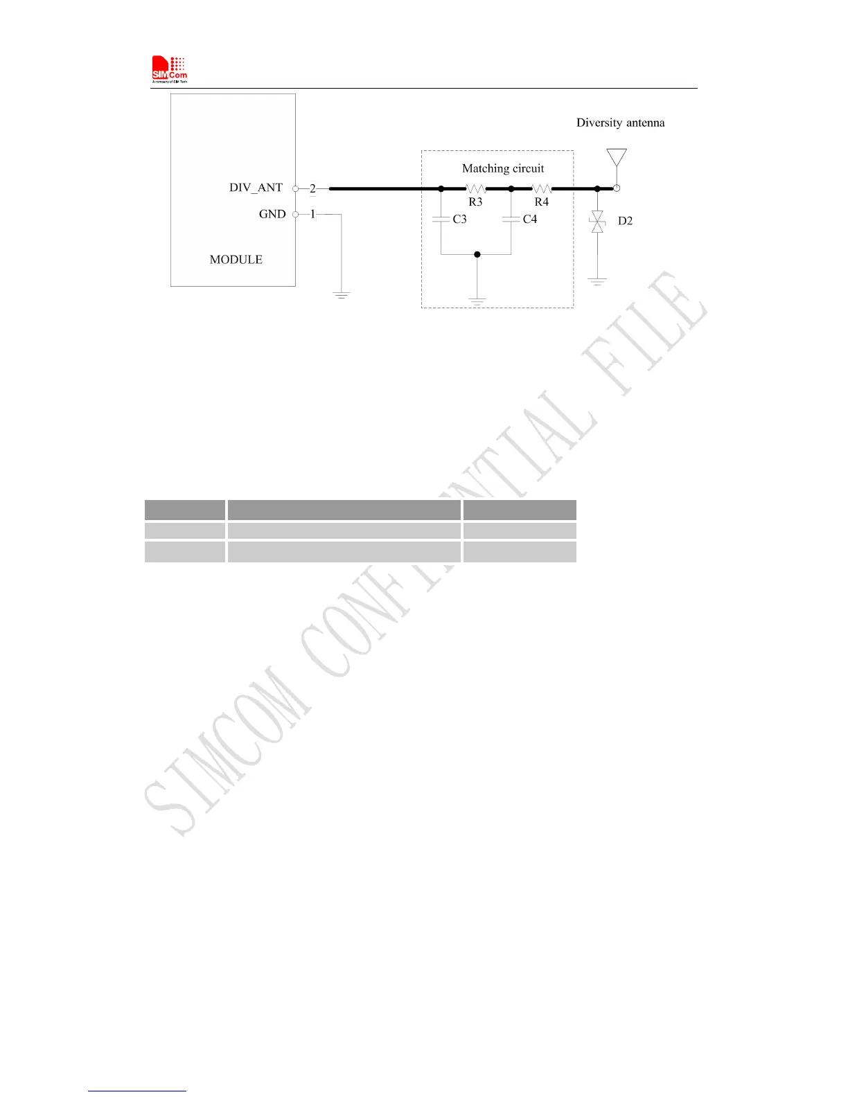
Figure 28: Antenna matching circuit (DIV_ANT)
In above figure, R3, C3, C4 and R4 are used for auxiliary antenna matching. By default, the R3, R4
are 0Ωresistors, and the C3, C4 are reserved for tuning. D2 is a TVS for ESD protection, and it is
optional for users according to application environment.
Two TVS are recommended in the table below.
Table 26: Recommended TVS
Note
:
SIMCom suggests the LTE auxiliary antenna to be kept on, since there are many high
bands in the designing of FDD-LTE. Because of the high insert loss of the RF cable and layout
lines, the receiver sensitivity of these bands above will have risk to meet the authentication
without the diversity antenna.For more details about auxiliary antenna design notice,please
refer to document [25]
To facilitate the antenna tuning and certification test, a RF connector and an antenna matching
circuit should be added. The following figure is the recommended circuit.
circuit should be added. The following figure is the recommended circuit.