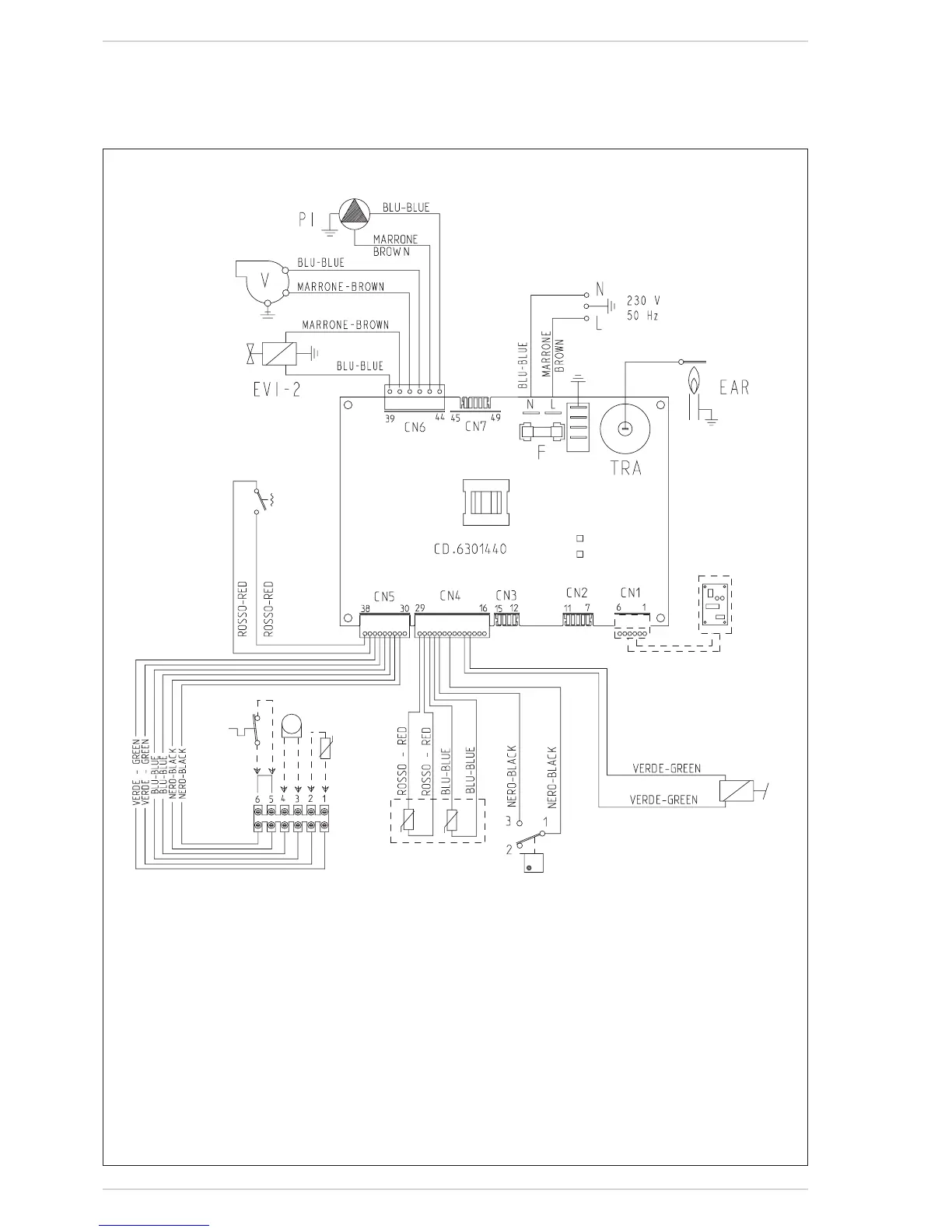
EasyManuals Logo

Sime FORMAT DGT 30i User Manual

Sime FORMAT DGT 30i
40 pages
To Next Page IconTo Next Page
To Previous Page IconTo Previous Page
Page #25 background imageLoading...
Page #25 background image
25
6.2.10 BOILER ELECTRICAL DIAGRAM
SM1/SM2
(3,3 VDC)
PF (24 VDC)
S.AUX
(3,3 VDC)
SE (3,3 VDC)
TA
(24 VDC)
M (17 VDC)
EXP (24 VDC)
PA
(24 VDC)
Fig. 16
“30 I - 30 E SYSTEM” models
KEY
F Fuse(1.6AT)
TRA Ignitiontransformer
PI Pump
V Fan
EAR Ignition/detectionelectrode
EV1-2 Gasvalvecoil
PF Airpressureswitch
M Modulator
SM1/SM2 Heatingsensor
PA Waterpressureswitch
TA Roomthermostat
SE Externalsensor
S.AUX Auxiliarysensor
EXP Expansioncardremotecontrol
(optional)
NOTE: Connect TA to connections 5-6 after having
removed the bridge.
CONNECTOR SPARE PART CODES:
CN4 code6319112
CN5 code6316253
CN6 code6316252

Table of Contents

Other manuals for Sime FORMAT DGT 30i

Questions and Answers:

Question and Answer IconNeed help?

Do you have a question about the Sime FORMAT DGT 30i and is the answer not in the manual?

Sime FORMAT DGT 30i Specifications

General IconGeneral
BrandSime
ModelFORMAT DGT 30i
CategoryBoiler
LanguageEnglish

Related product manuals