.
The table below gives the values to set
whenthesupplygasischanged:
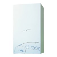
6.4.2.2 Adjusting valve pressure
(fig. 24)
Setmaximumandminimumpressureon
gasvalvesasfollows(fig.24):
– Connect a manometer to the intake
downstream of the gas valve (4 fig.
22).
Disconnect the valve VENT pressure
test point tube (5 fig. 22).
– Removethecap(1)fromthemodula-
tor.
- Puttheboilerinchimneysweepmode
(see section 6.4.4.2), ensure that ane
zonevalvesareopen.
– Pressthekey
againtoquitthefun-
ction.
– RefitthevalveVENTpipe.
– Remove the manometer, remembe-
ring to tighten the screw for closing
thepressuretestpoint.
– Put the plastic cap (1) back on the
modulator. Check all test points and
connectionsforgastightness.
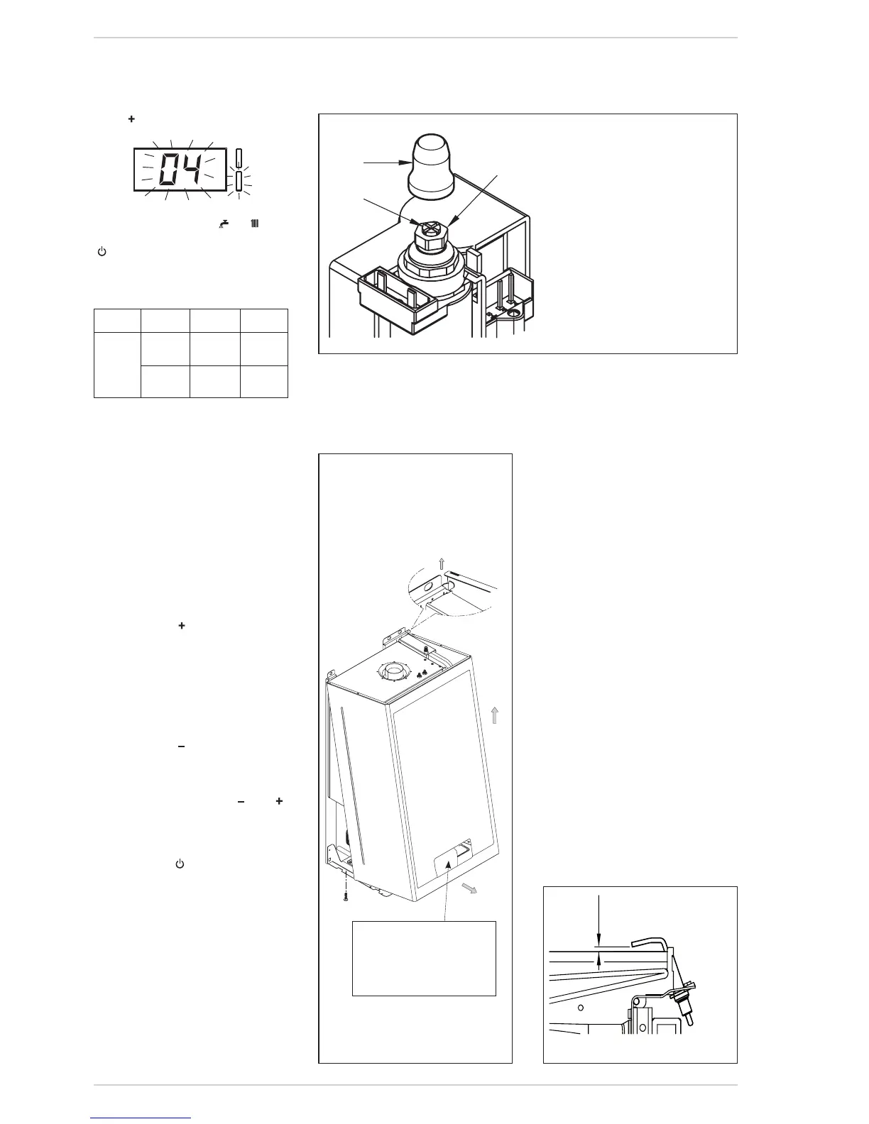
6.4.3 DISMANTLING
THE CASING (fig. 25)
The casing may be removed complete-
ly to facilitate boiler maintenance, as
showninfig. 25.Turn thepanel control
forwardforaccess totheinternal com-
ponentsoftheboiler.
6.4.4 MAINTENANCE
To guarantee functioning and efficien-
cy of the appliance, in respect of the
legal provisions in force, it must be
regularly checked; the frequency of the
checks depends on the type of instal-
lation and usage but this should be at
least annually.
Carry out the following procedure for
cleaningtheburner/heatexanger:
– Isolate the boilers electrical supply
andclosethegasisolationvalve.
– Removethe outercasingasshownin
fig.25;removethecombustioncham-
bercoverandtheburnercover.
– Idealyuseavacuumcleanerandasoft
brushtoremoveanydebris;takecare
nottodamagetheinsulationpanel.
- Clean the heat exchanger, removing
anydustorresiduefromcombustion.
- Whencleaning theheat exchangeror
theburner,chemicalproductsorsteel
brushesMUSTNOTBEUSED.
6.4.4.1 Ignition/Detection
electrode (fig. 27)
- Remove the casing, front panel and
sealedchambercovers.
- Unscrewthescrewsecuringtheelec-
trodeandremovefromtheburner.
- disconnecttheelectrodecable.
- Replacetheelectrodeandsetthegap
asshown.