The boiler must be installed in a fixed
locationandonlybyauthorisedperson-
nel in compliance with all instructions
containedinthismanual.
Furthermore, the installation must be
inaccordancewith currentStandardAS
5601andotherregulationsasapplicable.
Use the template supplied to position
allholes.
6.2.1 INSTALLATION
– Theseboilerscanbeinstalledinallnormal
domestic environments as aroomsealed
multifunctionboiler.
–
These boilers can also be installed in
partiallycovered areas,asper AS5601,
with a maximum ambient temperature
of60°Candaminimumambienttempe-
ratureof-5°C.Itisgenerallyadvisable
to install the boilers below weathered
roofs, on the balcony or in a protected
niche,toprotectthemfromexposureto
weatheringagents(rain,hailandsnow).
Allboilersprovideastandardantifreeze
function.
MINIMUMCLEARANCES
forINTERNALBOILERS
This Boiler must have the following cle-
arances:
Above200mm
Below200mm
Sides 50mm
Front 600mm
Min50mmtoanopenablepanel.
6.2.1.1 Anti-freeze function
The boilers are equipped with anti-fre-
eze function which activates the pumps
andtheburnerwhenthetemperatureof
thewatercontained insidethe appliance
drops to below value PAR 10. The anti-
freezefunctionisensured,however,only
if:
– theboileriscorrectlyconnectedtothe
gasandelectricitysupplycircuits;
– theboilerisconstantlyfed;
– theboilerignitionisnotlockedout;
– theessentialcomponentsofthe
boilerareallinworkingorder
Intheseconditionstheboilerisprotected
against frost down to an environmental
temperatureof-5°C.
ATTENTION: In the case of installation
in a place where the temperature drops
below 0°C, the connection pipes must
be protected.
6.2.2 COMPLEMENTARY
ACCESSORIES
The fixing jig code 8075427 is supplied
onrequest.Itallowstomounttheboiler
on wall and it is completed of installing
instructions.
6.2.3
CONNECTING UP SYSTEM
Toprotectthe heat systemfrom dama-
gingcorrosion, incrustationor deposits,
beforeinstallationitisextremelyimpor-
tant to clean the system using suitable
productssuchas,forexample,FERNOX.
Completeinstructionsareprovidedwith
theproductsbut,forfurtherinformation
pleasecontacttheHuntHeatingtechni-
caldepartment.
For long-term protection agains corro-
sion and deposits, the use of inhibitors
such as Fernox is recommended after
cleaning the system. It is important to
check the concentration of the inhibi-
tor after each system modification and
duringmaintenancefollowingthemanu-
facturer’spublishedinstructions.
The safety valve drainmustbeconnec-
ted to a collection funnel to collect any
discharge during interventions. If the
heatingsystemisonahigherfloorthan
theboiler,installtheon/offtapssupplied
inkitoptionalontheheatingsystemdeli-
very/returnpipes.
WARNING: Failure to clean the heating
system or add an adequate inhibitor
invalidates the appliance’s warranty.
Gasconnectionsmustbemadeinaccor-
dancewithcurrentstandardsandregula-
tions.Whendimensioninggaspipesfrom
the meter to the module, both capacity
volume (consumption) in m
3
/h and gas
densitymustbetakenintoaccount.
The sections of the piping making up
thesystemmust besuch astoguaran-
tee a supply of gas sufficient to cover
themaximumdemand,limitingpressure
loss between the gas meter and any
apparatus being used to not greater
than:
– 1.0 mbar for family II gases (natural
gas);
– 2.0mbarforfamilyIIIgases(butaneor
propane).
An adhesive data plate is placed insi-
de the front panel; it contains all the
technical dataidentifyingthe boiler and
the type of gas for which the boiler is
arranged.
6.2.3.1 Filter on the gas pipe
Thegas valveissuppliedexfactory with
aninletfilter,which,however,isnotade-
quate to entrap all the impurities in the
gasoringasmainpipes.
Topreventmalfunctioningofthevalve,or
incertaincaseseventocutoutthesafety
device with which the valve is equipped,
installanadequatefilteronthegaspipe.
6.2.4 SYSTEM FILLING
The charge pressure, with the system
cold,mustbebetween1 and 1.2 bar.
Fillingmustbedoneslowlysoastoallow
anyairbubblestobebledoffthroughthe
airvalves.
Should the pressure have risen well
above the limit expected, discharge the
overpressure byopening thepressure-
reliefvalve.
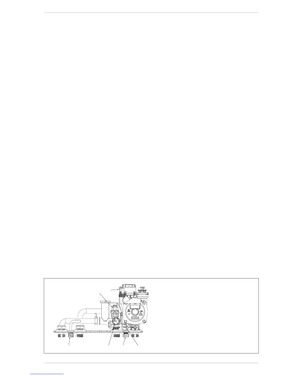
NB: In the SYSTEM version the filling is
done by the system filling connection
(item 10 fig. 8).
6.2.4.1 Emptying the system
Usethedrain ventto emptythesystem
(item5fig.8).
Turnofftheboilerbeforedoingthis.