to exitthe parameters section.
Thedisplayisshownautomaticallyafter
5minutes.
The parameters section contains the
alarms log, info and meters (display
only).
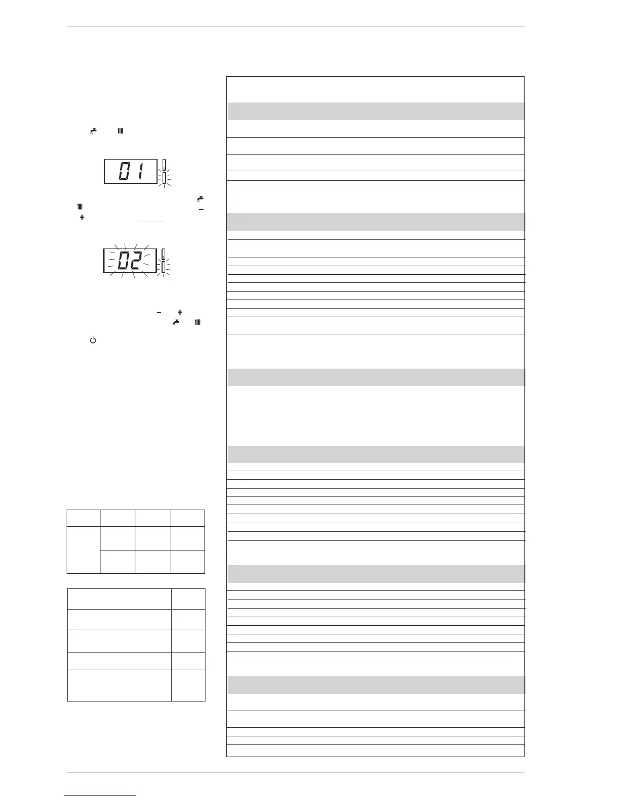
6.3.2.1 Replacing the board or
RESETTING parameters
If the electronic board is replaced or
reset,itisnecessarytoconfigurePAR01
andPAR02byassociatingthefollowing
valuestoeachtypeofboilertobeableto
restarttheboiler:
NOTE: the boiler panel has a label with
the values that have to be set for PAR 01
and PAR 02 (fig. 25).
BOILER GAS MODELS PAR 1
METHANE – 01
FORMAT (G20) 30 02
DGT LPG – 03
(G30/G31)
30 04
PARAMETERS INSTALLER
FAST CONFIGURATION
PAR DESCRIPTION RANGE UNITOF INC/DEC DEFAULT
MEASUREMENT UNIT SETTING
01 Combustionconfiguration --=ND = = “--”
1...8
02 Hydraulicconfiguration --=ND = = “--”
1...22
03 IlluminationofthegreenLED 0=Disabled = = 01
1=Enabled
04 Correctionofexternalprobevalues -5...05 °C 1 00
05 Timerblockofthekeys --=Disabled Min. 1 15
1...99
D.H.W. - HEATING
PAR DESCRIPTION RANGE UNITOF INC/DEC DEFAULT
MEASUREMENT UNIT SETTING
10 Boilerantifreeze 0...10 °C 1 03
11 Externalsensorantifreeze --=Disabled °C 1 -2
-9...05
12 Climaticcurvesetting 03...40 = 1 20
13 Minimumtemperatureheating 40...PAR14 °C 1 40
14 Maximumtemperatureheating PAR13...80 °C 1 80
15 Maximumpowerheating 30...99 % 1 99
16 Post-circulationtime 0...99 10sec. 1 03
17 Pumpheatingactivationdelay 0...99 10sec. 1 01
18 Re-ignitiondelay 0...10 Min. 1 03
19 ModulationD.H.W.flowmeter --=Disabled = = 01
1=Enabled
29 Anti-legionella(onlyD.H.W.tank) --=Disabled °C 1 “--”
50...80
PARAMETERS RE-SET
PAR DESCRIPTION RANGE UNITOF INC/DEC DEFAULT
MEASUREMENT UNIT SETTING
49* Resetdefaultparameters --,1 = = =
(PAR01-PAR02equal“---”)
* Should the boiler operate in an erratic manner, it is advisable to reset to “factory settings” by PAR 49 = 1
and PAR 1 and PAR 2 as specified in point 3.2.1.
ALARMS (visualization)
PAR DESCRIPTION RANGE UNITOF INC/DEC DEFAULT
MEASUREMENT UNIT SETTING
A0 Codeoflasterror = = = =
A1 Codeoflasterror-1 = = = =
A2 Codeoflasterror-2 = = = =
A3 Codeoflasterror-3 = = = =
A4 Codeoflasterror-4 = = = =
A5 Codeoflasterror-5 = = = =
A6 Codeoflasterror-6 = = = =
A7 Codeoflasterror-7 = = = =
A8 Codeoflasterror-8 = = = =
A9 Codeoflasterror-9 = = = =
INFO (visualization)
PAR DESCRIPTION RANGE UNITOF INC/DEC DEFAULT
MEASUREMENT UNIT SETTING
i0 Externalsensortemperature -9...99 °C 1 =
i1 C.H.1sensortemperature -9...99 °C 1 =
i2 C.H.2sensortemperature -9...99 °C 1 =
i3 D.H.W.sensortemperature -9...99 °C 1 =
i4 AuxiliarysensorAUXtemperature -9...99 °C 1 =
i5 Setofeffectiveheatingtemperature PAR13...PAR14 °C 1 =
i6 Levelsurveyflame 00...99 % 1 =
i7 Currenttothemodulator 00...17 10mA 1 =
i8 FlowrateD.H.W.flowmeter 00...99 l/min 1 =
COUNTERS (visualization)
PAR DESCRIPTION RANGE UNITOF INC/DEC DEFAULT
MEASUREMENT UNIT SETTING
c0 Numberhoursofoperationoftheburner 00...99 hx100
0,1from0,0to9,9
00
1from10to99
c1 Numberofignitionsoftheburner 00...99 x1000
0,1from0,0to9,9
00
1from10to99
c2 Numbertotaloftheerrors 00...99 x1 1 00
c3
Numberoftimetheinstallerparametersaccessed
00...99 x1 1 00
c4
OftimetheOEMparametershavebeenaccessed
00...99 x1 1 00