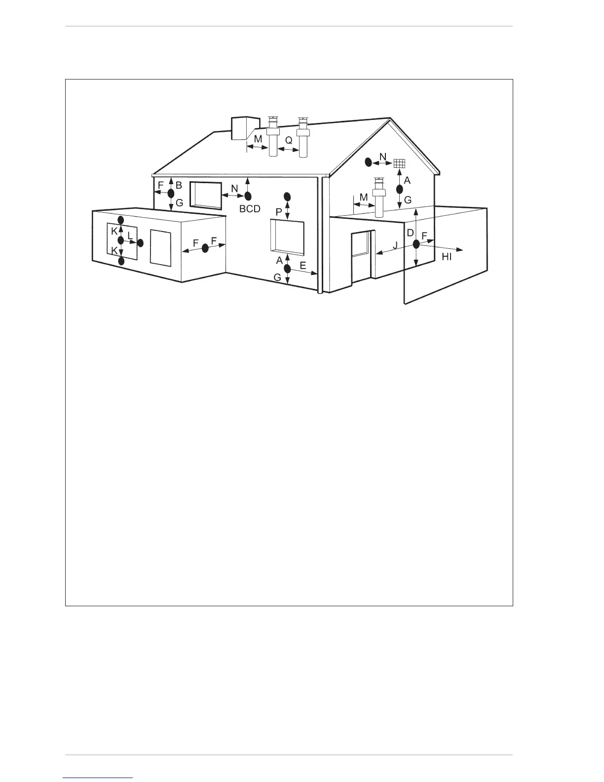
Terminal position Minimum spacing
A Directlybelowanopenablewindow,airvent
oranyotherventilationopening 300mm 12in
B Belowguttering,drainpipesorsoilpipes(*) 75mm 3in
C/D Beloweaves,balconiesorcarportroof 200mm 8in
E Fromverticaldrainpipesorsoilpipes 75mm 3in
F Frominternalorexternalcorners 300mm 12in
G Aboveadjacentground,rooforbalconylevel 300mm 12in
H Fromaboundaryorsurfacefacingtheboiler 600mm 24in
I Fromaterminalfacingtheterminal 1,200mm 48in
J Fromanopeninginthecarport
(egdoor,windowintodwelling) 1,200mm 48in
K Verticallyfromaterminalonthesamewall 1,500mm 60in
L Horizontallyfromaterminalonthesamewall 300mm 12in
M Horizontallyfromaverticalterminaltoawall 300mm 12in
N Horizontallyfromanopenablewindoworotheropening 300mm 12in
P Aboveanopenablewindoworotheropening 300mm 12in
Q Fromanadjacentverticalterminal 600mm 24in
(*) For condensing boilers this distance can be reduced to 25 mm without effecting boiler
performance, but it will be necessary to protect the surfaces from the effects of con-
densate
– If the terminal discharges into a pathway or
passagewaycheck thatcombustion products
willnotcausenuisanceandthattheterminal
willnotobstructthepassageway.
– Wherethe lowest part of the terminal ist-
tedlessthan2m(78in)aboveground,above
abalconyoraboveaatrooftowhichpeople
haveaccess,theterminalMUSTbeprotected
byapurposedesignedguard.
– Wheretheterminalisttedwithin850mm(34
in)of aplastic orpaintedgutter, or450 mm
(18in)ofpaintedeaves,analuminiumshield
atleast1,500mm(59in)longmustbettedto
theundersideofthepaintedsurface.
– The air inlet/outlet ue duct MUST NOT be
closerthan25mm(1in)tocombustiblema-
terial.
– In certain weather conditions the terminal
mayemitaplumeofsteam.Thisisnormalbut
positionswherethiswouldcausea nuisance
shouldbeavoided.
NOTE
The following information is an extract from AS 5601-2004. This information is subject to copyright of the AGA and Standards Australia and is sup-
plied only as a reference. Every installer should have a copy and be familiar with this standard before installing this appliance.
MINIMUM CLEARANCES REQUIRED FOR BALANCED FLUE TERMINALS, FAN-ASSISTED FLUE TERMINALS, ROOM-SEALED APPLIANCE TERMI-
NALS OR THE TERMINALS OF OUTDOOR APPLIANCES.
Fig.14/a
6.2.9 ELECTRICAL WIRING
A standard 3 pin plug and cord are
provided.Itis essentialthatthe correct
polarity is maintained as should they
be reversed the boiler will continually
lockout.Shouldtheleadbe damaged,it
mustbe replacedbya speciallead from
HUNTHEATING.Thepowersupplymust
be single-phase 230V - 50 Hz through
a main switch protected by a 3 A fuse
withadistanceofatleast3mmbetween
contacts.
NOTE:
The boiler must be connected with an
efficient grounding system. HUNT shall
not be held liable for injury or damage
resulting from failure to ground the
boiler.
ATTENTION:
The boiler controls only put the unit in
standby. Before working on the applian-
ce isolate it from the power supply.
6.2.9.1 Thermostat
Connection
Removetheboilercasing,tiltthecontrol
paneland connecttheroomthermostat
to the 6 pole terminal board as indica-
tedintheboilerelectricaldiagram(see
paragraph 6.2.10)afterhavingremoved
theexistingbridge.
The thermostat to be used must be of
a class conforming to the standard EN
60730.1(cleanelectricalcontact).