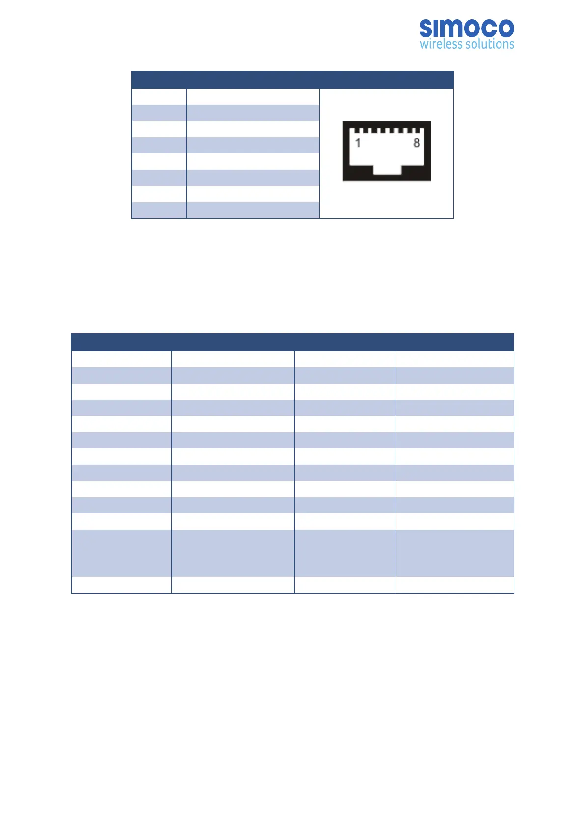
Pin Description
1 Tx Data+, balanced I/P 1
2 Tx Data-, balanced I/P 2
3 Rx Data+, balanced O/P 1
4 NC
5 NC
6 Rx Data-, balanced O/P 2
7 NC
8 NC
Table 3: Ethernet RJ45 Connector Pin-outs.
S1 Facilities Connector
The 25-way D Type facilities connector can be programmed for any combination of
digital inputs and outputs. The connector pin-outs for the Facilities Connector are
shown below in Table 4.
Pin Function Pin Function
1 Digital Input 14 Digital Output
2 Digital Input 15 Digital Output
3 Digital Input 16 Digital Output
4 Digital Input 17 Digital Output
5 Digital Input 18 Digital Output
6 Digital Input 19 Digital Output
7 Digital Input 20 Digital Output
8 Digital Input 21 Digital Output
9 GPS Rx + GPS Rx + 22 GPS Rx -
10 GPS Rx + GPS Tx + 23 GPS Tx -
11 1PPS Rx + 24 1PPS Rx -
12
Digital to Analogue
Converter (DAC) Out-
put
25 0 V
13 Supply Voltage
Table 4: Facilities Connector Pin-outs.
The Digital Outputs are open collector and able to sink 300 mA each; the total for all
outputs must not exceed 600 mA.
Digital inputs are active low. Digital high voltages should not exceed 20 V.
The GPS Rx and 1PPS Rx connections are Differential RS422.
The “DAC Output” connection is between 0 V and 5 V and software controlled to
indicate various functions e.g. Received Signal Strength Indication (RSSI) level.
Doc Number: TNM-I-E-0041 Revision 1.6 Page 25