4
4007ES Operator’s Manual (579-1165)
User Interface
Overview:
The user interface is used to operate the FACP.
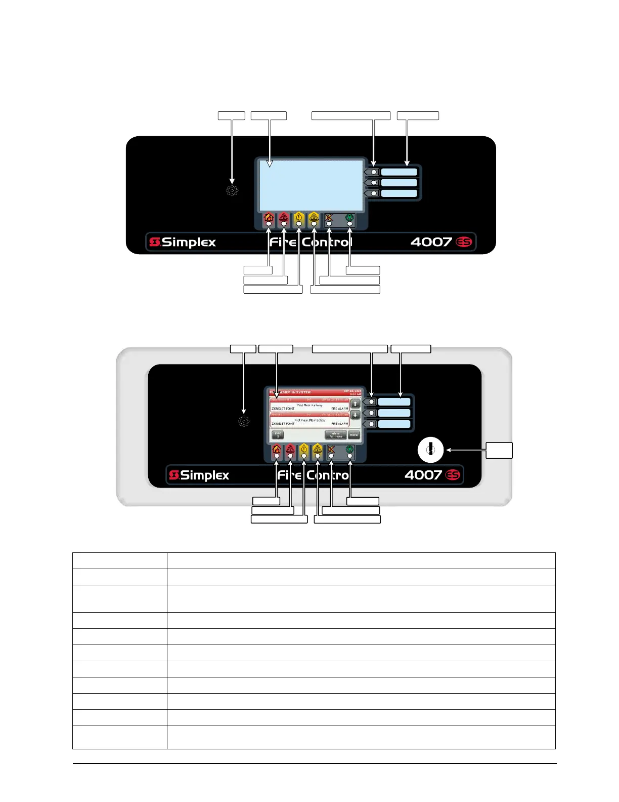
Figure 1. 4007ES User Interface
Figure 2. Color Touchscreen LCD Annunciator User Interface
Table 1. The FACP User Interface is made-up of the following components:
Touchscreen Used as the panel’s input/output interface.
Piezo Emits tones during Alarm, Trouble, Pri2 and Supervisory conditions.
Bi-color User-
Defined LEDs
Associated with the three custom-configured user buttons. The top two LEDs can be either
yellow or red. The bottom LED can be either yellow or green.
Slide-in Labels Used to describe the functions of the user buttons.
Fire LED Indicates a fire alarm when flashing and an acknowledged alarm when steady on.
Priority 2 LED Indicates a Priority 2 condition when flashing and an acknowledged condition when steady on.
Supervisory LED
Indicates a Supervisory condition when flashing and an acknowledged condition when steady on.
Trouble LED Indicates a Trouble state when flashing and acknowledged Trouble when steady on.
Alarm Silence LED Indicates an alarm has been silenced when steady on.
Power LED Indicates AC power is applied to the panel when steady on.
Keyswitch
(Only on the Color Touchscreen LCD Annunciator) Allows interaction with the panel if the key is
used.
Power LED
Alarm Silenced LED
Trouble LED
Priority 2 LED
Supervisory LED
Fire LED
Slide-in LabelsBi-Color User Defined LEDs
Piezo
Touchscreen
Keyswitch
Power LED
Alarm Silenced LED
Trouble LED
Priority 2 LED
Supervisory LED
Fire LED
Slide-in LabelsBi-Color User Defined LEDs
Piezo
Touchscreen
User Interface