Note: The 4098-9771, 4098-9772, 4098-9773 and 4098-9794 Sounder Bases have a 9-position DIP Switch. The first eight DIP Switches set
the sounder base address. DIP Switch Position 9 is set to OFF or ON depending on the sounder base power source. When the sounder
base is connected to a 24 VDC power source, DIP Switch Position 9 is set to “OFF” and the 24 VDC power is supervised by the sounder
base. When the sounder base is powered by the panel’s Notification Appliance Circuit (NAC), DIP Switch Position 9 is set to “ON” and
the power is supervised by the NAC and not the sounder base. The 4098-9770 base has the same layout, but it does not have sounder
functionality. It uses an 8-way DIP switch only.
4.4.3 Address setting for the 2120 CDT System
1. Using the 2120 Job Configuration Report, find the entry for the sensor base, 4098-9775, 4098-9776, 4098-9792 and 4098-9789
only, you are installing. The CUSTOM LABEL column indicates the location while the DEVICE ADDRESS column indicates the switch
setting data.
2. Using the switch setting data for the base you are installing, set the address of the base. See Setting the address of the base for
the location of the switches. Use a non-metallic stylus, or the equivalent, to set the switches.
3. Double-check the location and address of the sensor base before proceeding to the electrical installation, see Figure 3.
4.4.4 Address Setting for the 4010, 4020, 4100+, 4100U, 4100ES, 4010ES, 4007ES, 4008, or 4120
System
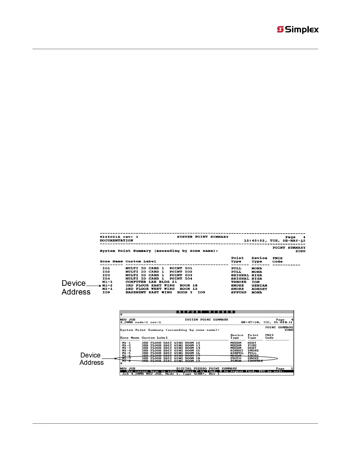
1. Using the Programmer’s Report, find the entry for the sensor base you are installing. The device ADDRESS and CUSTOM LABEL
are located in the SYSTEM POINT SUMMARY under “M”. For example, Address M1-7, is circled in Figure 12. M1 is the addressable
channel and '-7' is the device address on the channel. For a base with Address M1-7, ensure Address 7 is set on the base’s DIP
Switches (SW1).
2. Using the example given in Step 1 as guideline, set the address on the base using the information in Figure 13. See Setting the
address of the base for the location of the DIP Switches. Use a non-metallic stylus, or the equivalent, to set the switches.
3. Mark an address label with the appropriate address for the base by shading a label box for each base DIP Switch in the ON
position. Apply the label near the DIP Switch on the base.
4. Double-check the location and address of the sensor base before proceeding to electrical installation.
Figure 11: 4020 Programmer’s Report
Figure 12: 4100+, 4100U, 4100ES, 4010ES, 4007ES, 4120, 4008, or 4010 Programmer’s Report
The figure below shows the address DIP Switch settings. Refer to Compatibility and testing for compatibility information for the various
FACPs.
Note: The 4020, 4100+, 4100U, 4100ES, and 4120 systems support up to 127 devices on each MAPNET II channels. The 4010, 4100U,
4100ES, 4010ES, and 4007ES support up to 250 devices on the IDNet channel. The 4008 supports up to 200 devices on the IDNet channel.
page 24 574-709 Rev. AP
4098 Detectors, Sensors, and Bases Application Manual