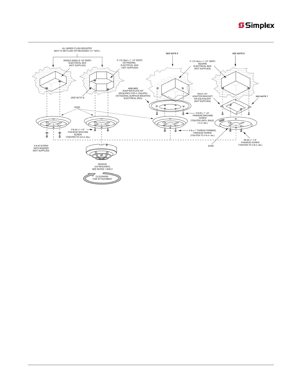
Figure 3: Typical detector or sensor mounting
Note 1:
To lock and unlock a detector or sensor into a base, complete the following steps:
1. Break off the plastic lock tab to engage the locking mechanism.
2. To lock a detector or sensor into a base, turn the unit until the locking tab clicks into place.
3. To unlock a detector or sensor, insert the blade of a screwdriver into this slot and pull down on the handle. Turn and remove the
detector or sensor, see Figure 3.
Note 2:
Refer to Compatibility and testing for detailed information about compatible detectors.
Note 3:
Bases with relay modules require that a 1.5 inch, or 38.1 millimeter extension ring, not supplied, is mounted to the 4 inch square or
octagonal electrical box to meet the space requirement of the relay cube and its wires. The relay modules cannot be used in single-gang
electrical box installations. Ensure the relay cube 4098-9822 is installed in the electrical box directly behind the sensor base.
Note 4:
Use the Adapter Plate Kit, 4098-9832, when mounting the following detectors or sensors to a surface mounted 4 inch, or 10.16 centimeter,
square or octagonal box:
4098-9794, 4098-9770 and 4098-9771.
For this installation only, ensure the adapter plates are installed with the textured side towards the electrical box.
Note 5:
4098-9775, 4098-9776, 4098-9780, 4098-9789, 4098-9791, 4098-9792 and all detector bases flush mounted (box to be flush mounted or
recessed 1/4” max).
Note 6:
4098-9770, 4098-9771 and 4098-9794 only flush mounted (box with adapter bracket to be flush or recessed 1/4” max).
Note 7:
4098-9772, 4098-9773: Use Adapter plate kit 4098-9863 to mount 4098-9772 or 4098-9773 to 4” square box.
page 13 574-709 Rev. AP
4098 Detectors, Sensors, and Bases Application Manual