SECTION 2
INSTALLATION WIRING
General Notes
1. Ground the TCC (use the green screw provided to attach the ground wire).
2. Using appropriate fasteners, mount the TCC on or in the wall.
3. Shift P4 jumper on CPU Board 2 (see Figure 1 on page 5) from pins 2 & 3 to pins 1 & 2.
.
Jumper P4 hooks up a rechargeable battery which provides power for time-tracking and program retention
during AC power outages of seven or more days.
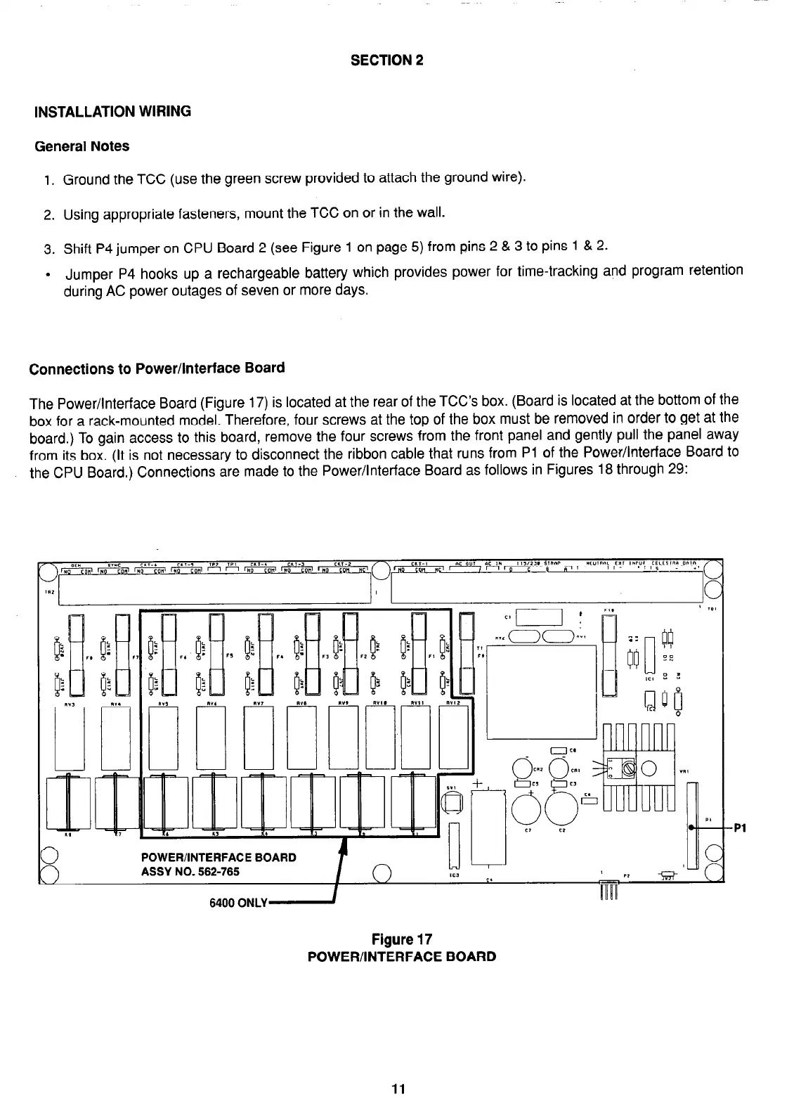
Connections to Power/Interface Board
The Power/Interface Board (Figure 17) is located at the rear of the TCC’s box. (Board is located at the bottom of the
box for a rack-mounted model. Therefore, four screws at the top of the box must be removed in order to get at the
board.) To gain access to this board, remove the four screws from the front panel and gently pull the panel away
from its box. (It is not necessary to disconnect the ribbon cable that runs from Pi of the Power/Interface Board to
the CPU Board.) Connections are made to the Power/Interface Board as follows in Figures 18 through 29:
Figure 17
POWER/INTERFACE BOARD
Pl
11