APPENDIX C
WWV INTERFACE BOARD -
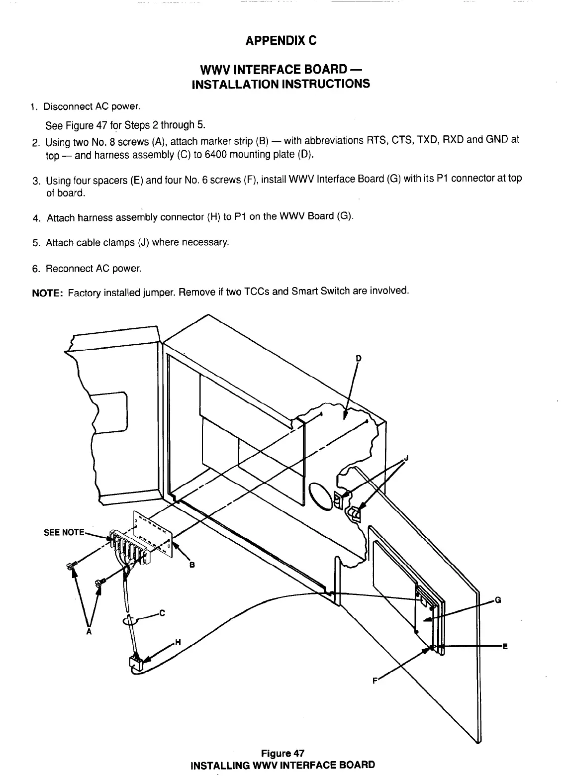
INSTALLATION INSTRUCTIONS
1. Disconnect AC power.
See Figure 47 for Steps 2 through 5.
2. Using two No. 8 screws (A), attach marker strip (B) -with abbreviations RTS, CTS, TXD, RXD and GND at
top - and harness assembly (C) to 6400 mounting plate (D).
3. Using four spacers (E) and four No. 6 screws (F), install WWV Interface Board (G) with its Pl connector at top
of board.
4. Attach harness assembly connector (H) to Pl on the WWV Board (G).
5. Attach cable clamps (J) where necessary.
6. Reconnect AC power.
NOTE:
Factory installed jumper. Remove if two TCCs and Smart Switch are involved.
SEE
Figure 47
INSTALLING WWV INTERFACE BOARD
38