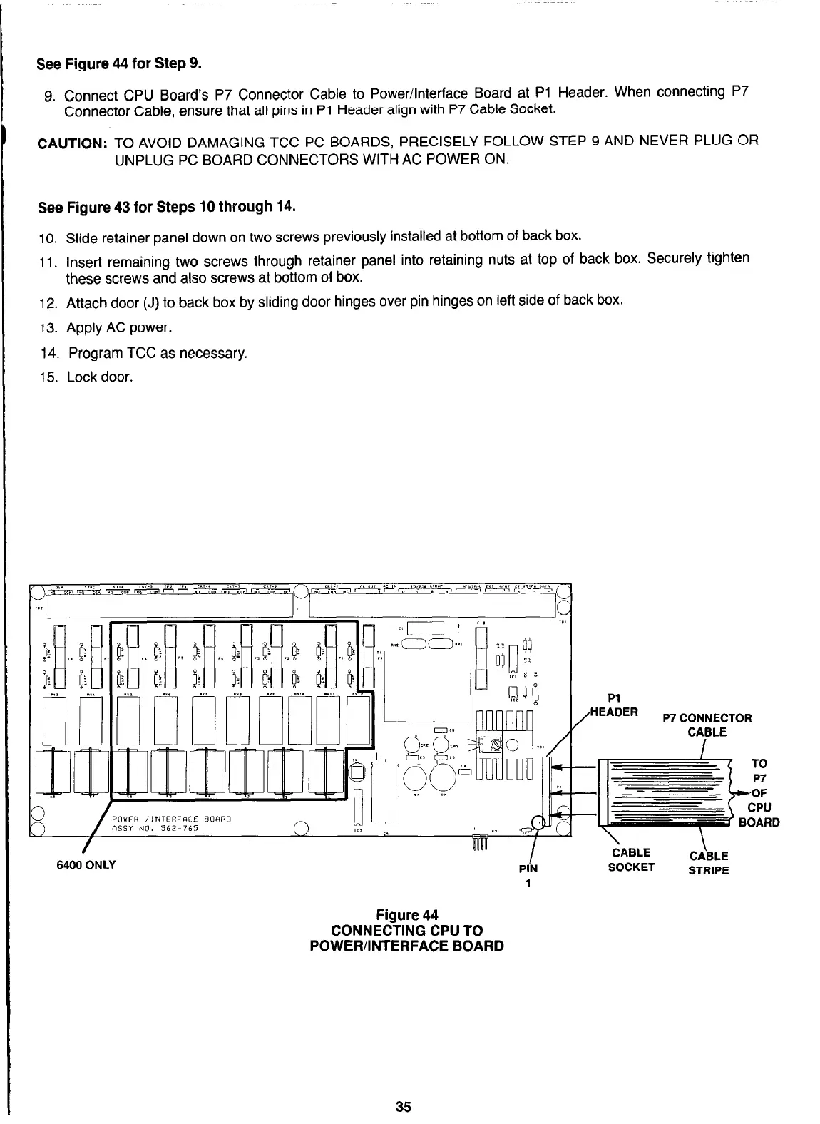
See Figure 44 for Step 9.
9. Connect CPU Board’s P7 Connector Cable to Power/Interface Board at Pl Header. When connecting P7
Connector Cable, ensure that all pins in Pl Header align with P7 Cable Socket.
CAUTION: TO AVOID DAMAGING TCC PC BOARDS, PRECISELY FOLLOW STEP 9 AND NEVER PLUG OR
UNPLUG PC BOARD CONNECTORS WITH AC POWER ON.
See Figure 43 for Steps 10 through 14.
10. Slide retainer panel down on two screws previously installed at bottom of back box.
11. Insert remaining two screws through retainer panel into retaining nuts at top of back box. Securely tighten
these screws and also screws at bottom of box.
12. Attach door (J) to back box by sliding door hinges over pin hinges on left side of back box.
13. Apply AC power.
14. Program TCC as necessary.
15. Lock door.
SOCKET SOCKET
STRIPE STRIPE
1 1
Figure 44 Figure 44
CONNECTING CPU TO CONNECTING CPU TO
POWER/INTERFACE BOARD POWER/INTERFACE BOARD
TO
P7
*OF
CPU
BOARD
35