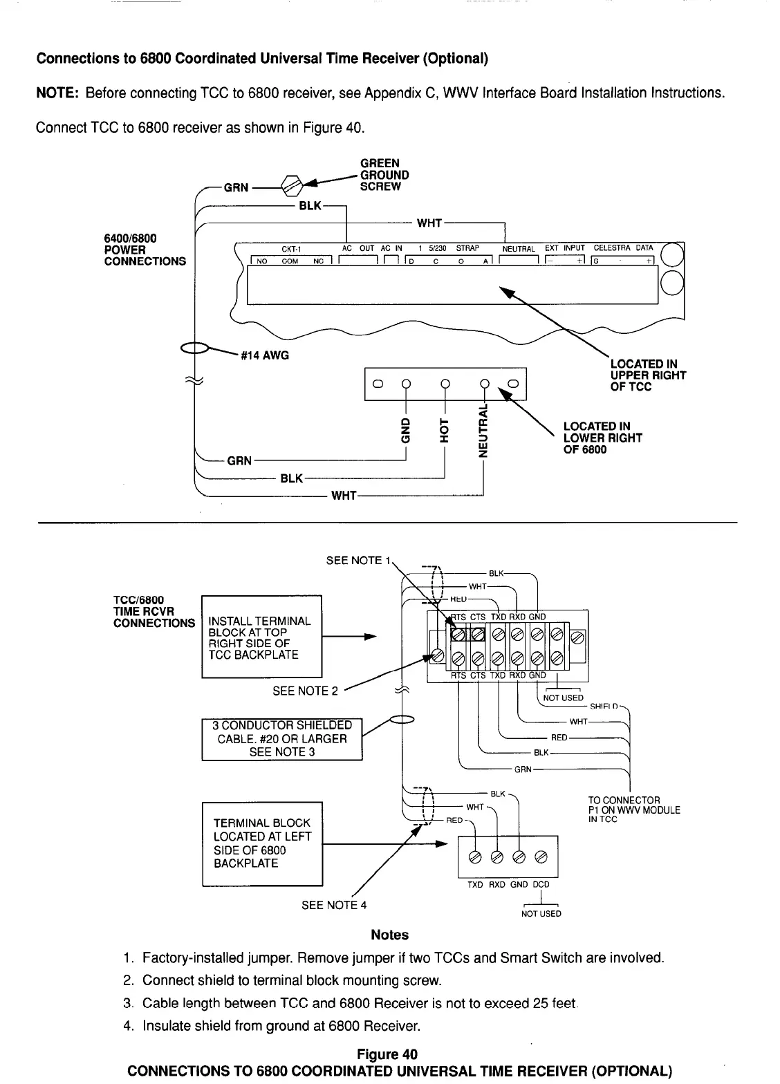
Connections to 6800 Coordinated Universal Time Receiver (Optional)
NOTE: Before connecting TCC to 6800 receiver, see Appendix C, WWV Interface Board Installation Instructions.
Connect TCC to 6800 receiver as shown in Figure 40.
Y
I
/
WHT
6400/6800
POWER
AC OUT AC IN 1 5,230 STRAP
NE”TRAL EXT INPUT CELESTRA DATA
CONNECTIONS
COM NC i r-----l n 1 D C 0 Al - I- IS - +I
== #14 AWG
OF 6800
TCC/6800
TIME RCVR
CONNECTIONS
SEE NOTE 1
INSTALL TERMINAL
BLOCK AT TOP
RIGHT SIDE OF
TCC BACKPLATE
t-
-/
SEE NOTE 2
SHIEI
Notes
NOT USED
1. Factory-installed jumper. Remove jumper if two TCCs and Smart Switch are involved.
2. Connect shield to terminal block mounting screw.
3. Cable length between TCC and 6800 Receiver is not to exceed 25 feet.
4. Insulate shield from ground at 6800 Receiver.
Figure 40
CONNECTIONS TO 6800 COORDINATED UNIVERSAL TIME RECEIVER (OPTIONAL)
28