ARM
mm
(in.)
DD15 12V AC42 – – 150 Kgm 2 A –
HLD350 12V AC12 200 (7,9)
350
(770)
610
(5400)
12 2,5-8 A
–
Steering gear interface: Connects to quadrant or tiller.
* For stern drive power assisted steering only.
1. For 12V drive units the motor voltage is stepped
down by the autopilot computer when operating from
24V supply.
2. The specified autopilot computer is necessary to
achieve max drive unit capacity.
3. Recommended operational thrust or torque is 70% of
listed peak value.
4. Typical average power consumption is 40% of listed
maximum value.
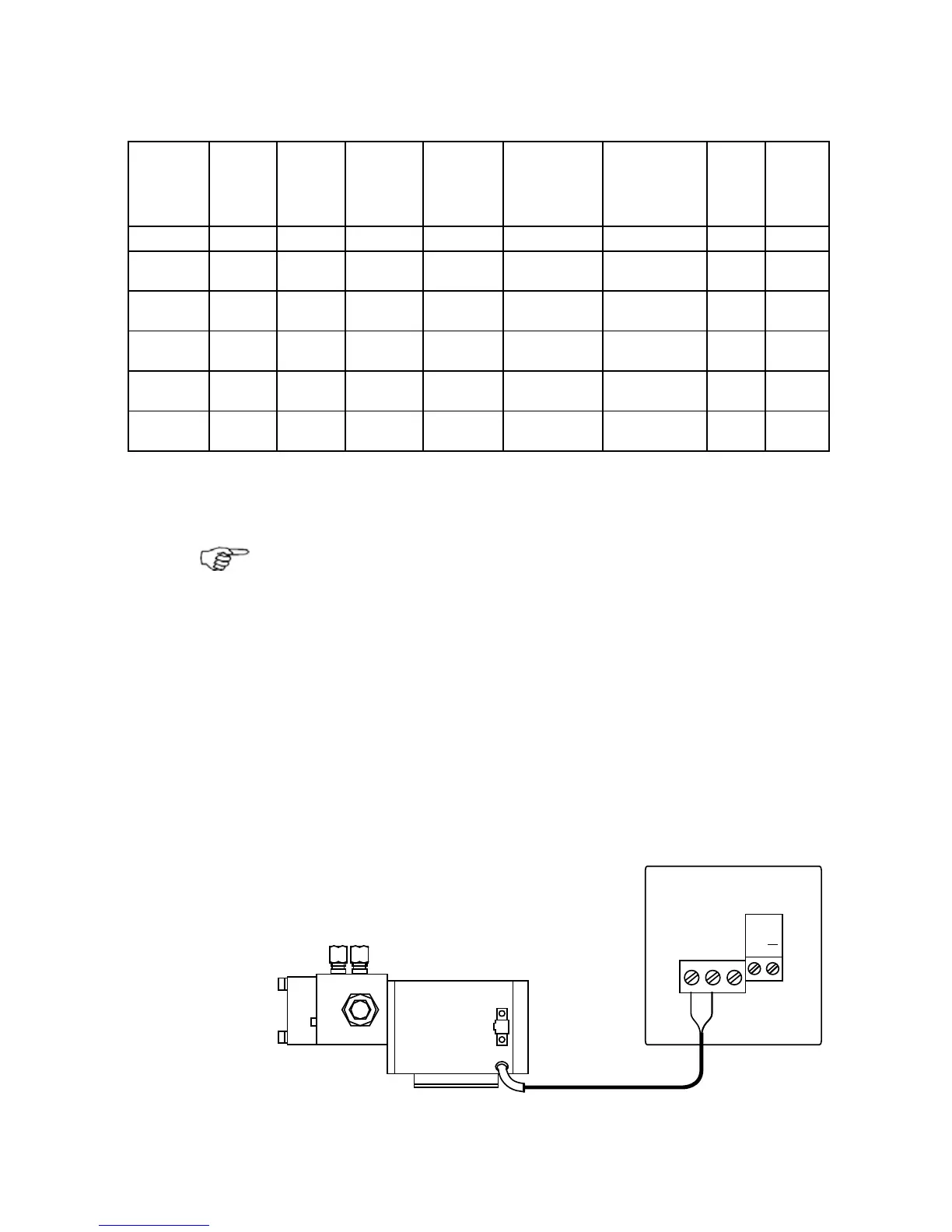
Connecting a reversible pump
+
DRIVE
DRIVE
ENGAGE
SOL.-MOTOR
SOL.-MOTOR
SOL.GND
AC12 Autopilot Computer
SIMRAD Reversible Pump
Figure 2-10 Connecting a reversible pump