EasyManuals Logo

Simrad AP70 Installation Manual

Simrad AP70
84 pages
To Next Page IconTo Next Page
To Previous Page IconTo Previous Page
Page #18 background imageLoading...
Page #18 background image
18 |
Mounting | AP70/AP80 Installation Manual
Panel (ush) mount
1. Attach the mounting template to the selected mounting position
2. Drill pilot holes for the 4 hole saw cuts and for the 4 self tapping screws used to secure the
unit. If using M4 machine screws use a 5 mm (0.20 ”) drill bit
3. Use a 25 mm (1 “) hole saw to cut the four corner radius
4. Cut along the dotted line and remove waste material
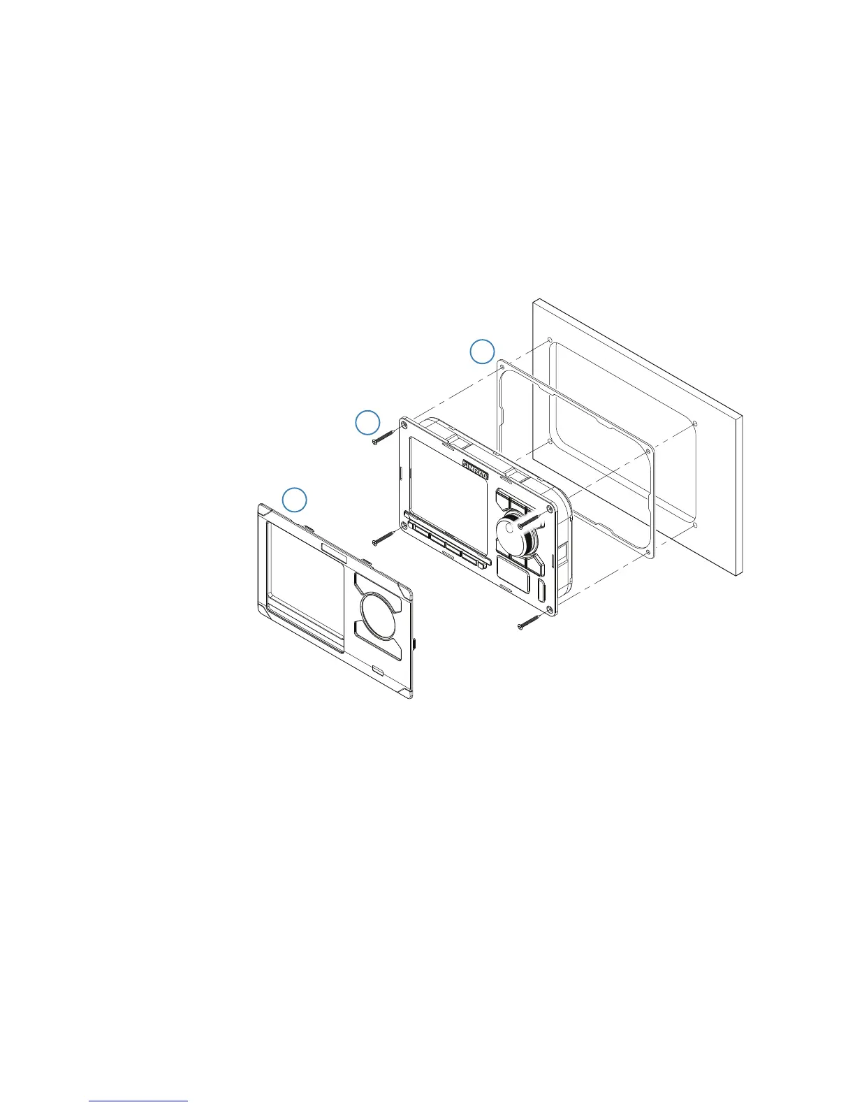
5. Peel backing off the gasket and apply it to the unit (A)
6. Connect the cables to the rear of the unit before placing the unit into the console
7. Secure the display to the surface with 4 screws (B)
8. Firmly clip the bezel in place (C)
¼ Note: For AP80 the bezel may not be used for flush/low profile installations.
A
B
C

Other manuals for Simrad AP70

Questions and Answers:

Question and Answer IconNeed help?

Do you have a question about the Simrad AP70 and is the answer not in the manual?

Simrad AP70 Specifications

General IconGeneral
TypeAutopilot Control Unit
Power Supply12/24 V DC
Operating Temperature-15°C to +55°C
Waterproof RatingIPx6
InterfaceNMEA 0183, NMEA 2000
Operating Voltage12/24 V DC
Water ResistanceIPx6
DisplayLCD
Control ModesAuto, Nav, Wind
Storage Temperature-25°C to +70°C

Related product manuals