14 |
Introduction | AP70/AP80 Installation Manual
Computer boards
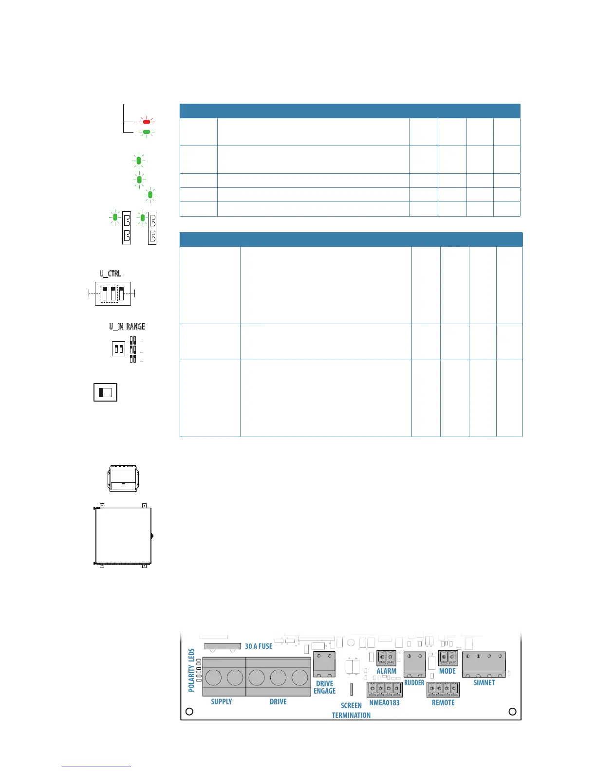
Indicator diodes and switches
Indicator diodes and switches are available on the boards as shown in the tables below.
LED Description AC70 AD80 SD80 SI80
Polarity
check
Red: wrong polarity
Green: correct polarity
x x
CPU
1Hz alternating green: CPU is running correctly
Rapid flashing: Application program is missing
x x x x
HS Green: Handshake output is on x x
RX Living green: Serial data is received x x
SOL Green: Solenoid command is given x
Switch Description AC70 AD80 SD80 SI80
U_CTRL
Selection of internal ±10 V or external
reference voltage for analog voltage control
output.
¼ Note: For 4-20 mA current control,
switches must be set to internal ref.
voltage
x
U_IN RANGE
Range setting of analog voltage input signal
for rudder feedback, follow up wheel or
remote DP control
x x
SIMNET
TERMINATION
ON (to the left) or off setting of 120 ohm
CAN bus termination.
¼ Note: Termination must be set to ON
when the board is at one end of the
CAN bus backbone, otherwise it must
be set to OFF.
x
AC70 board
Drive computer board for rudder or propeller (i.e. Voith Schneider) for reversible motor or
galvanic non-isolated solenoids.
Includes:
• SUPPLY - power supply 12/24 V in
• DRIVE - output for Motor or solenoid command
• DRIVE ENGAGE - output for clutch/bypass valve or automode signal for oil flow valve etc
• ALARM - Output for external alarm buzzer
• NMEA 0183 - in/out for IEC 61162-1, -2 and NMEA 0183
• RUDDER - Input for frequency rudder feedback
• REMOTE - Input for NFU steering lever
• MODE - Input for external mode selector
• SIMNET - connection to CAN network