| 7
Introduction | AP70/AP80 Operator Manual
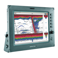
3 Rudder bar
Rudder position indicator with digital and analog readout.
The digital readout shows 1 bar per 1° rudder angle up to 40°. Rudder angle above 40° will
have a non-linear indication in the outer left/right part of the bar.
Direction indicators are turning red (port) and green (starboard) when rudder movement is
commanded. The direction arrows are only shown when rudder feedback is available.
Rudder angle *
C
ommanded
rudder dir
ection
* Showing commanded rudder angle in systems with analog steering without rudder
feedback.
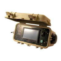
4 Status panel
The following mode abbreviations are used:
S: Standby
FU: Follow Up
NFU: Non Follow Up
A: Auto heading
ND: No Drift
N: Nav
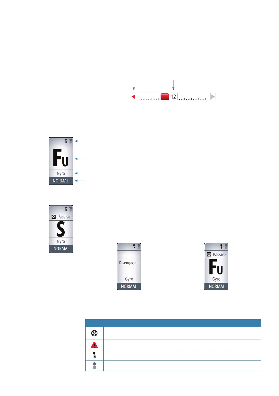
If the autopilot is operated from another unit, this is shown in the mode indication fi eld.
If the autopilot is controlled by an external system selector or by an external follow-up, the
mode indication will be replaced as below.
Autopilot disengaged by external system selector Rudder controlled by external follow-up
Available status icons are shown below. Only active icons will be visible.
Icon Description
Icon available if one or more thrusters are installed. The icon will be shaded when
the trusters are unavailable for steering
Active alarm message. Red icon for alarms, yellow for warnings
Control unit locked
Screen alive indication - white and black “balls” fade-swap color
Status icons
Mode indication
Steering reference
Active work pro le