Simrad GC80/GC85 Compact Gyro Compass
6 20221511 / D
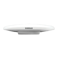
2.1 GC80 Compact Control unit
The Control unit includes the control panel for the gyro
compass.
A flush mount kit (part number 27101757) may be ordered from
Simrad for remote installation of the control panel. Refer Flush
mounting the control panel, page 37.
^i^oj
dvol
buq
afpm pbq
afj
i^jm
qbpq
^`h
bkq
pfjo^a=d`UM
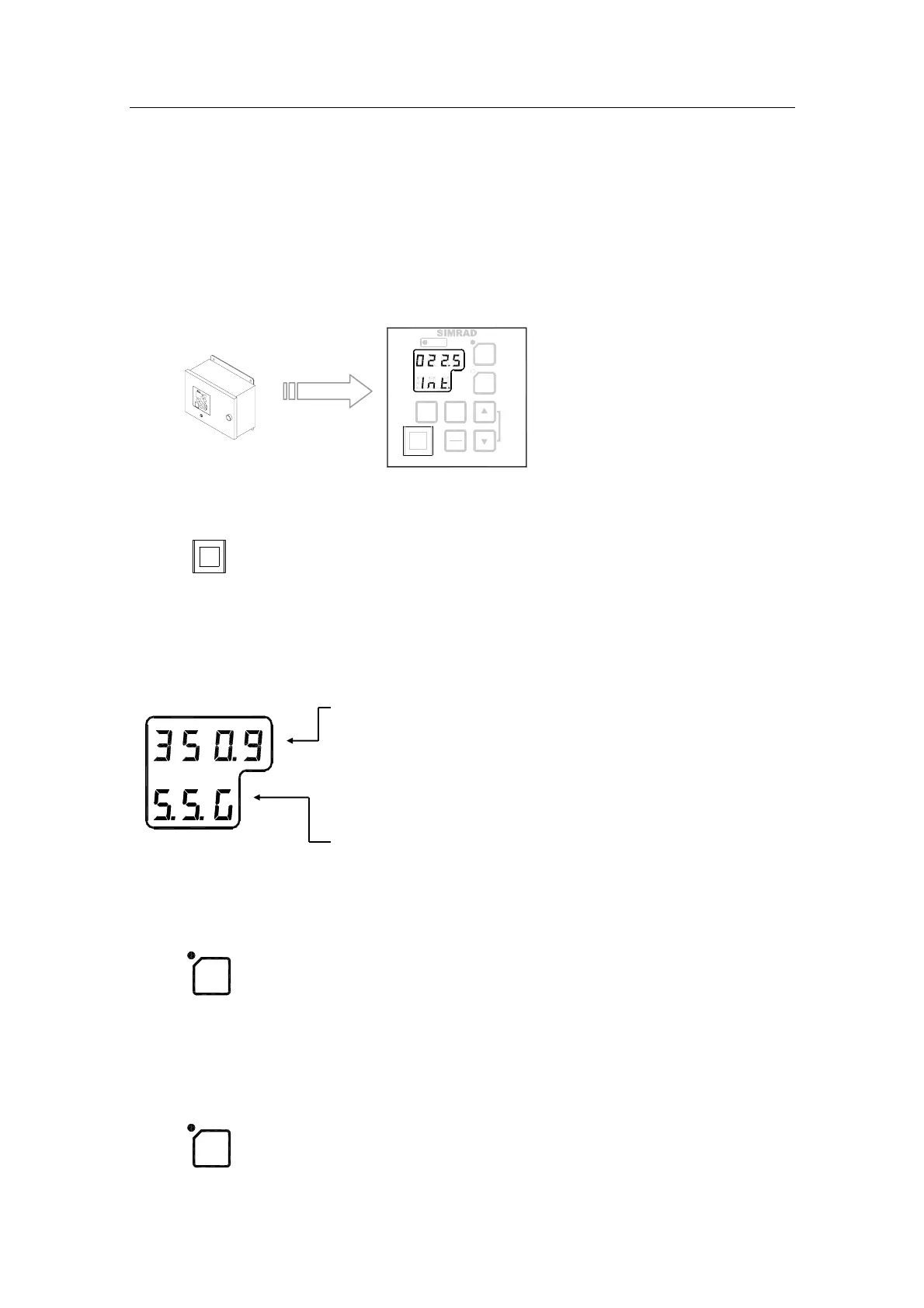
POWER Button
mltbo
Used for switching the gyro system ON. The button will be lit to
indicate that power is applied to the system. Refer System Start-
up and Shut-down, page 10.
Display
The LCD displays data in two rows: the upper row shows data
and the lower row shows active mode.
- The Data indicator consists of four 7-segments red
LEDs. The indicator is used for displaying the vessel’s
bearing, latitude and speed. Refer Displaying present
settings, page
13.
The Data indicator is also used for displaying alarm
codes as described from page
19 onwards.
- The Mode indicator consists of three 7-segments green
LEDs. The Mode indicator displays codes used for
identifying input type for bearing, latitude and speed.
GYRO Button
dvol
Used for selecting the gyro compass as the active heading
reference source. The status lamp is lit to indicate that the gyro
system is active.
Refer Selecting active compass, page 12.
EXT Button
buq
Used for selecting the external heading source as the heading
reference. The status lamp will be lit to indicate that the external
heading reference source is active.
Refer Selecting active compass, page 12.