Simrad GC80/GC85 Compact Gyro Compass
42 20221511 / D
5.4 Grounding the units
All units in the GC80/GC85 system should have a proper
ground connection from the unit’s ground terminal.
The wires should be as short as possible and have a cross section
of at least AWG13 (2.5mm
2
).
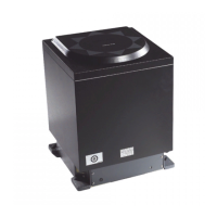
MASTER COMPASS
COMPACT
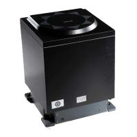
CONTROL UNIT
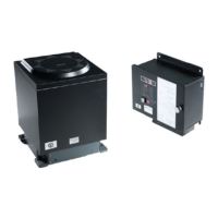
POWER SUPPLY
UNIT (OPTION)
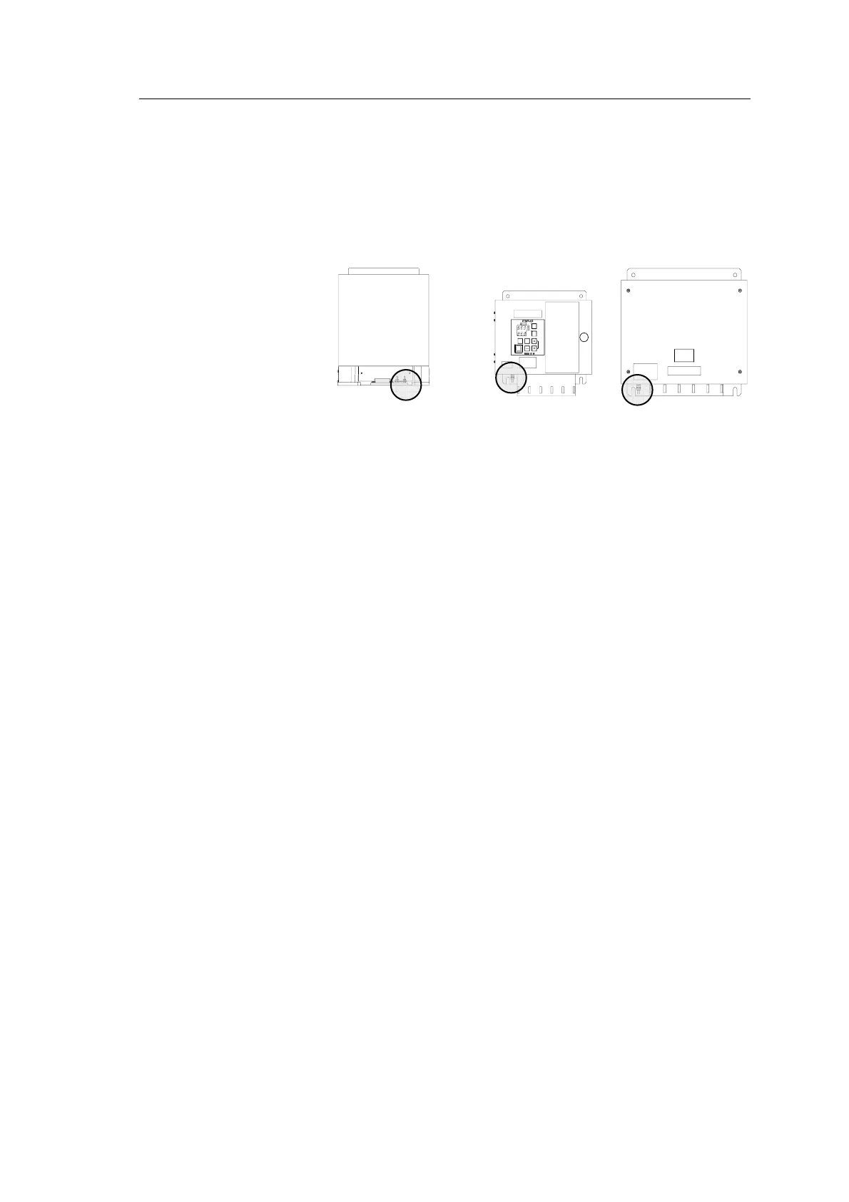
5.5 Dip-switch and jumper settings
GC80 and GC85 gyro systems include several dip switches and
jumpers. With the exception of two switches on the ICIF board
in the Control unit, no switches have to be set when installing
the system. These two switches are set to configure the Control
unit to match type of gyro system (GC80 or GC85), and to
activate an external heading sensor.
Note! These dip switch settings are read when the system is started.
Any changes when the system is running will therefore not take
affect before the system is restarted.
For a complete list of dip switch settings, refer to
DIP SWITCH
SETTINGS, page
89.