|
7
Display installation | MO Series User Manual
Display installation
It is recommended that the unit be powered and connected to a video source to assist in
selecting a suitable mounting location, prior to irreversable modication of the vessel’s helm
station. When planning the display location, the following points should be considered to
ensure safe, comfortable and reliable operation:
• Convenience - the mounting location should be easily accessible to allow operation of the
controls and should enable easy viewing of the display.
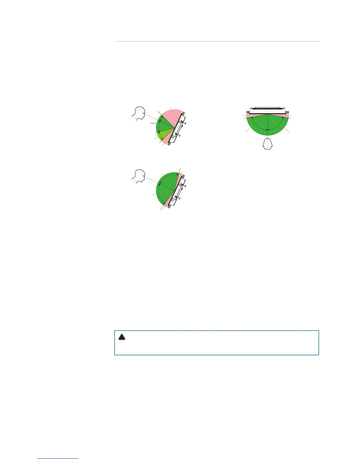
• Viewing angle - the viewing angle inuence the viewability of the monitor. The recom-
mended viewing angles relative to perpendicular are shown in the illustrations below.
MO16
MO19
Horizontal viewing angles
A: Optimum viewing angle
B: Good viewing angle
C: Poor viewing angle or obstructed view
MO24
Vertical viewing angles
• Access - there must be sucient space behind the display to allow cable connections to the
rear connectors, avoiding tight bends in the cable. Also ensure there is sucient access for
tightening wing nuts/screws on the mounting brackets, where used.
• Interference - the selected location should be far enough away from devices that may
cause interference, such as motors, generators and radio transmitters/receivers.
• Magnetic compass - mount the display at least 1 metre (3 ft.) away from a magnetic
compass.
• Environment - to prevent overheating, do not restrict airow at the rear of the display unit;
ensure that there is adequate ventilation, particularly if the display unit is pod-mounted. If the
space behind the display is air conditioned or cooled by a fan, it will help in keeping the unit’s
temperature down when mounted in direct sunlight. The display should be protected from
physical damage and excessive vibration. Although the display unit is waterproof from the
front when installed correctly, it is good practice to mount it in a protected area away from
prolonged and direct exposure to rain and salt spray.
Warning: Damage incurred to monitor through failure to provide adequate ventilation
could invalidate your warranty. Do not recess device in to an enclosure shared with a heat
source. e.g. engine compartment.
Cutout template
Use the supplied scale template to help mark up the cutout area.
¼ Note: Always check the template dimensions against the physical monitor to ensure
dimensions are correct, prior to making the cutout.
Fixing options
The MO series monitors can be dash or bracket mounted (using optional VESA adaptor).
When dash mounting, unit should be tted using the rear mounted dash mount brackets,
and bezel screws from the front. Exclusion of the dash mount bracket will greatly increase
strain on bezel screws and adjacent bezel plastics, and is not recommended.
2
A
C
C C
C
B
A A
40°
70°
20°
80° 80°
A
C
C
A
80°
80°