Page 35
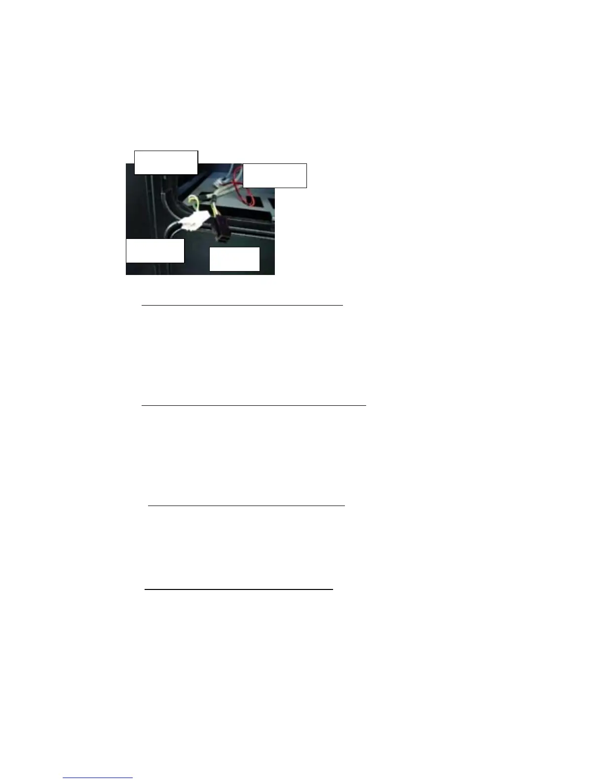
2) There are 4 electric connectors, the P1 (10 pins), P2 (4 pins), P3 (2 pins) and
P4 (2 pins) for Coin Validator / Bill Acceptor & Coin Meter interfacing to the
Sega I/O circuit. The pin assignments for each connector are:
P1 (10 pins White plug : for coin validator)
1 ---------- GND (wire colour GREEN)
2 ---------- +12V (wire colour YELLOW)
7 ----------- COIN SW1 in Sega I/O BD (wire colour BROWN)
8 ----------- COIN SW2 in Sega I/O BD (wire colour WHITE)
P2 (4 pins : for bill acceptor power & 12V lamp)
1------------ 110V AC(R)
2------------- 110V AC(T)
3------------- +12V (wire colour BROWN)
4------------- GND (wire colour WHITE)
P3 (2 pins : for coin meter for chute #1) {always ACTIVE with Electronic
Mech}
1------------ COIN METER 1 for Sega I/O BD (wire colour BROWN)
2------------- +5V (wire colour WHITE)
P4 (2 pins : for coin meter for chute #2) {SPARE meter connection}
1------------ COIN METER 2 for Sega I/O BD (wire colour YELLOW)
2------------- +5V (wire colour GREEN)
3) Attach the coin chute door and coin selector. Then, perform the wiring referring to
the electric schematic #1 of the SCU provided in session 10.1 to determine the
correct connection method.
P1 (10p)
P2 (4p)
P3 (2p)
P4 (2p)