F1...MONITOR
F2...TELEVISION
© 1983 Sinclair Research Ltd
2.2.2 This indicates that most of the system is working. If the QL does not power up, and display the expected copyright screen, switch off and
repeat the power-up operation two or three times. It is possible for the QL to lock-up on start-up and appear lifeless.
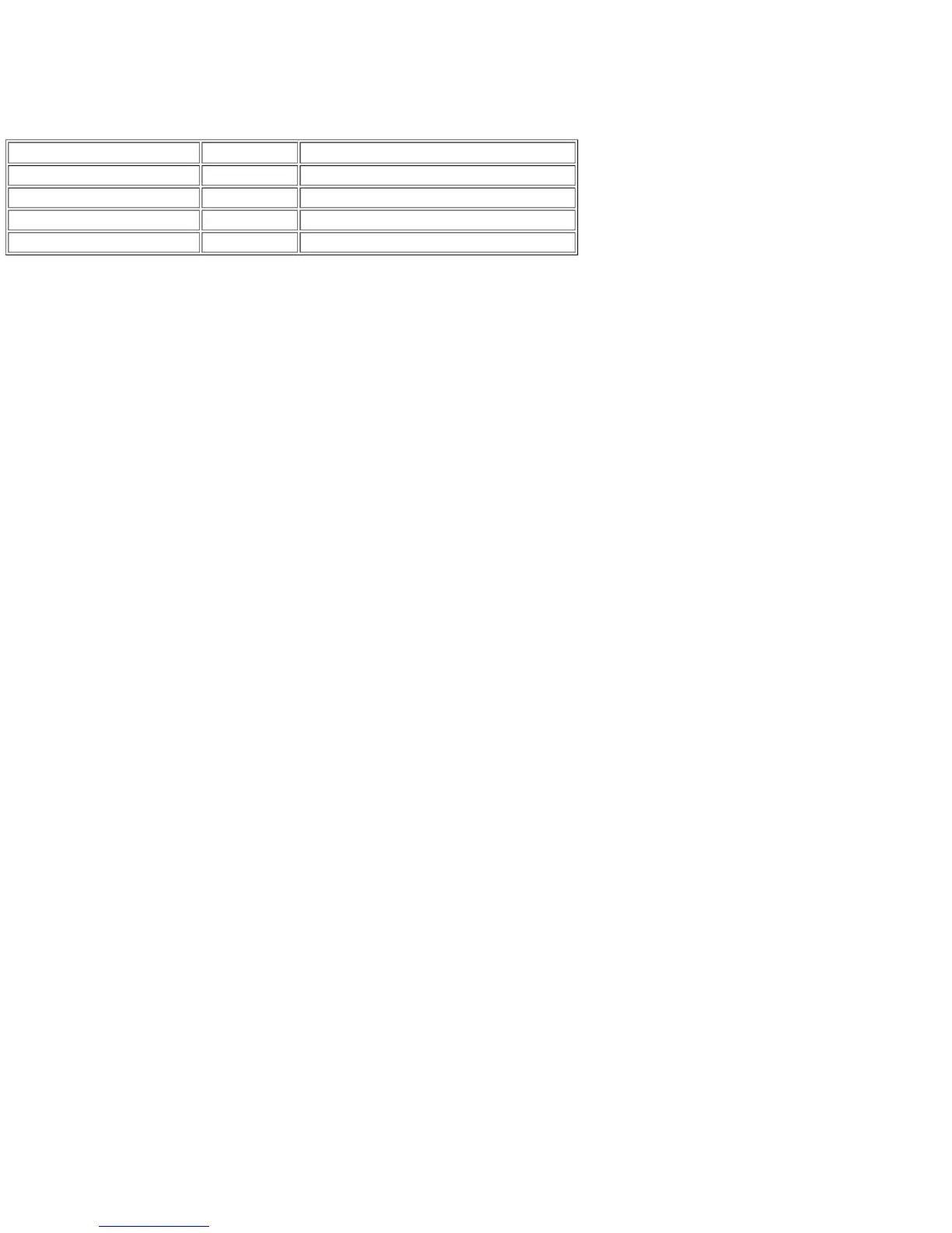
2.2.3 Lack of a copyright screen indicates a fundamental failure. First check voltages as set out in the table below.
FUNCTION CIRCUIT REF WAVEFORM/VOLTAGE
± 12 V voltage regulator input + side of D26 15.6 V a.c. ± 2.0 V
+ 5 V voltage regulator input + side of C41 + 9.0 V a.c. ± 2.0 V
+ 12 V voltage regulator output FT side of C38 + 12.0 V d.c. ± 0.25 V (no discernible ripple)
+ 5 V voltage regulator output FT side of C42 + 5.0 V ± 0.15 V (no discernible ripple)
2.2.4 The state of the display screen provides a good indication of the possible fault. Three general categories of fault display may be isolated.
2.2.5 A completely blank screen on switch-on is often caused by a faulty IC22 (8301). Since this is a plug-in component it can easily be substituted.
If this does not cure the problem, suspect a video fault and if it has not already been done, plug in both a monitor and a TV and check for video
output. If a replacement IC22 is not available, check that the clock signal to the CPU, and the RGB output signals are present.
2.2.6 If the RAM test is seen to be starting up before the system crashes, it means that the 8301 is working and that the ROM is being read and the
program is starting to be executed correctly. The start of the RAM test is indicated by the display of a fine pattern , of green, white, red and black
dots (tweed pattern) which move quickly down the screen and disappear. Fault-finding would start with the RAMs in this instance.
2.2.7 If the screen displays a geometric pattern (for example, red and green vertical bars), it means that the 8301 is working properly but is not
actually starting to execute the ROM code, it is not overwritng the RAM data. It is possible that the 8301 clock to the CPU is missing, or again that
RAM is faulty. An absent CPU can also give the same effect.
2.2.8 If the machine reaches the end of the RAM test, displays a geometric pattern and then reverts to a blank screen it could mean any one of the
following:
1. possible ROM fault,
2. problem with communication to IC23 (8302) or IC24 (IPC) - check that crystal X4 is oscillating and check for activity on the serial link betwen
the 8302 and the IPC (pins 29, 35 on IPC),
3. lack of communication between the 8302 and the IPC - this would inhibit the copyright prompt,
4. a continuous interrupt to IC18 (CPU) - this causes the CPU to loop up in trying to service its interrupts.
2.2.9 If the ROM enable signal (pin 33, 8301) is not present, the ROM is unable to excute correct code. If, on switch-on, random flickering patterns
are displayed, accompanied by excited beeping noises this suggests a faulty ROM. If the ROM is functioning but the RAM is not, then the screen
displays a white or green screen. This testifies that there is something wrong with the RAM.
2.2.10 The RAM test is divided into two parts, the first where it checks that it is possible to store ones, zeros and random pattern in every RAM
location, and the second part a few seconds later when it checks that the stored data is still there. A white screen means that the first part of the test
has failed and a green screen means that the second part has failed.
2.2.11 A green screen can mean either that memory is not being refreshed or that there is a possible short in one of the address or data lines
causing mis-routing of a bit of data. Check visually for shortcircuits across pins or address data lines in the, RAM area itself and then further afield
(e.g. at the CPU). It may then be necessary to carry out checks using an ohmmeter. Bear in mind that it is possible to obtain misleading readings
when, for example, the meter is feeding back through the CPU.
2.2.12 If the screen is not quite pure white or green and has either very narrow vertical stripes, or a vertical pattern of dots, this indicates that one bit
in the system is faulty, either as a result of a fault within one of the RAM chips or of a short-circuit across a data/address line. In order to pin-point
the faulty RAM chip, proceed as follows:
1. Take a probe and connect one end to ground.
2. Touch the probe on the data pin of each RAM in turn and observe the screen.
3. As the probe short-circuits a data line, a vertical black line or series of black lines appears on the screen. When this black line coincides with
whatever pattern is on the screen, dots or stripe(s), then the offending chip has been found. In fact, since the two banks of RAM are connected
together via the data bus it could be an IC from either bank (e.g. either IC1 or IC9). With this example, IC1 would need to be changed since
this is part of the memory mapped area of the store. In general, a long vertical stripe suggests a data line short-circuit, and dots suggest a
RAM fault.
2.2.13 If RESET is pressed and a 'tweed' pattern is seen on the screen for a certain time and it then reverts to white, this suggests that some failure
has been found in the second bank of RAM.
2.2.14 To summarise, if on power up a white or green screen is displayed, it indicates that the RAMs are in general working, and that the machine
is very close to being fully operational. It suggests a data or address line short-circuit or a faulty RAM chip.
2.2.15 If it is plain that the machine has not really started performing the RAM check at all, check for the regular occurrence of the DTACK signal
(pin 31, CPU). If this is not present the RAM test can never be initiated. Check for a short-circuit on the DTACK line and check the 8301, particularly
the DSMCL signal. A high level on the latter disables the 8301.