FIGURE 1.1 RS232 LINK
4.10 On receipt of a start bit, IC24 is interrupted, and a subroutine clocks in the data bits, synchronised by the baud rate generator. The data, up to
about 20 bytes per RS232 channel, is tnen buffered in IC24. At the same time, IC24 receives commands (and sends reports) via the serial link with
IC18 which i-s controlled by IC23. When IC24 receives a command from IC18 to empty one of its buffers, it does so, down the serial link via IC23.
4.11 With the QL acting as the DCE data and control is managed in a similar way utilising different IC25 and IC26 receivers/drivers.
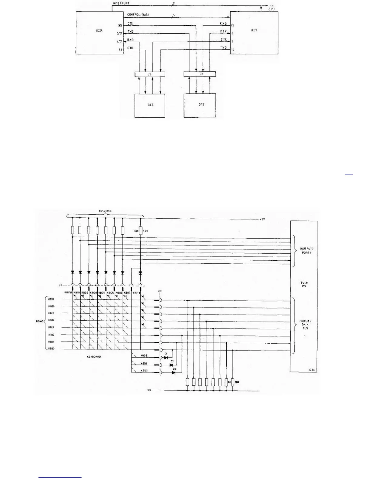
4.12 Keyboard Monitor. Under program control the 8049 systematically scans the keyboard, recording which keys have been pressed. Figure 1.2
shows the way the keyboard is connected. It consists of an 8 x 8 matrix with one key, the shift key, connected to three input lines. The intersection of
each row and column is bridged by a normally open contact. Pressing the key closes this switch. The row 'outputs' and column 'inputs' are shown
connected to separate connectors J11 and J12, one to the port 1 outputs of IC24 and the other to the data bus inputs. Pull-down resistors R17 to
R24 ensure that when none of the key-switches are closed row inputs KBO0 to KBO7 remain low.
FIGURE 1.2 KEYBOARD MATRIX INTERCONNECTIONS
4.13 When the keyboard scanning routines are entered (KBOn is output, KBIn is input) the 8049 performs successive I/O read cycles setting each
KBO0 to KBO7 line low in turn. At the same time the I/O port 1 inputs are scanned.
4.14 There are a total of eleven diodes used for isolation. Eight of these, D4 through D11 are isolation diodes which isolate the different rows from
each other. Three of the diodes D1 to D3 provide individual isolation for the Shift Control and Alt keys so that these keys have diodes in series with
them in both directions of the matrix. They are thus fully isolated.
4.15 Joystick. Connectors J3 and J4 provide a FIRE input and the four switch inputs for each of two joysticks. One line is not used. J3 and J4 are
connected in parallel with keyboard connectors J11 and J12.
4.16 Loudspeaker Operation. During the execution of a BEEP instruction the IPC writes to port 2, P21 thus switching on transistor TR1 and driving