Control mode:P
Range:0~2
Data size:16bit
Display mode:Decimal system
Parameter function:When the P2 group is given a position command, the multi section position switch mode is chosen.
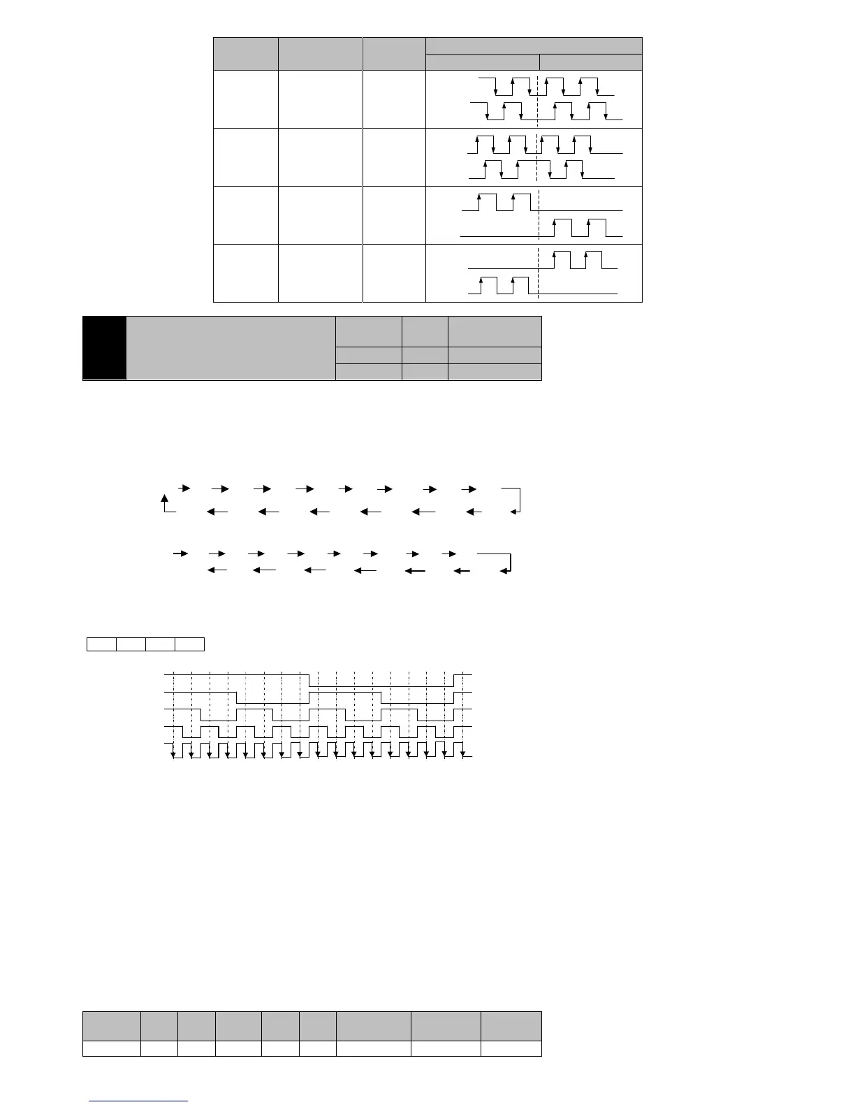
P1-03=0:Press the 16 section position from the start of the PR1 cycle.
P1-03=2:By external DI input switching operation as stipulated in the table 7-2. DI terminals must be set to 5(CMD0), 6(CMD1),
7(CMD2), 8(CMD3) and 9(CTRG)function.
DI default is low level effectively, if 4 road(5/6/7/8)DI input information in the following way to form a number D of bit 4:
NOTE:
1 : I t w i l l n o t t a k e e f f e c t t h a t i f c h a n g e s t h e c u r r e n t p e r i o d o f p a r a m e n t s i n t h e o p e r a t i o n
when P1-03=0 or 1,these paraments will only be effective in the next run.
2 : T h e s e g m e n t h a s i m p l e m e n t e d w i l l b e c l e a r e d t h a t i f c a n m a k e O F F o r p o w e r d o w n i n
t h e o p e r a t i o n w h e n P 1 - 0 3 = 0 o r 1 . A t t h e m o m e n t , i f d i r e c t l y t o r u n a g a i n , t h e c u r r e n t
position as a starting point ,since Pr1starts execution.
3 : T h e m u l t i s t a g e p o s i t i o n c o m m a n d e x e c u t i o n t r i g g e r e d b y f a l l i n g e d g e C T R G w h e n
P1-03=2,please set corresponding DI input terminal low level effectively.
4 : O n l y t h e e x e c u t i o n o f a p o s i t i o n c o m m a n d h a s f i n i s h e d , t h e r e s p o n s e t o a n o t h e r
command whenP1-03=2.
In the process of a position command execution, servo drive will not terminate the current position command execution by DI
terminal state change.
When the current position commad execution has finished, the servo drive in a wait state, according to the current DI terminal state
executes the corresponding segment of position instruction after receives the CTRG falling edge.
Table7-2internal position instruction multistage (DI)function
 Loading...