SETTING
THE
TIMING-INDICATOR
PIN
(MACHINES 281-22 AND 281-24)
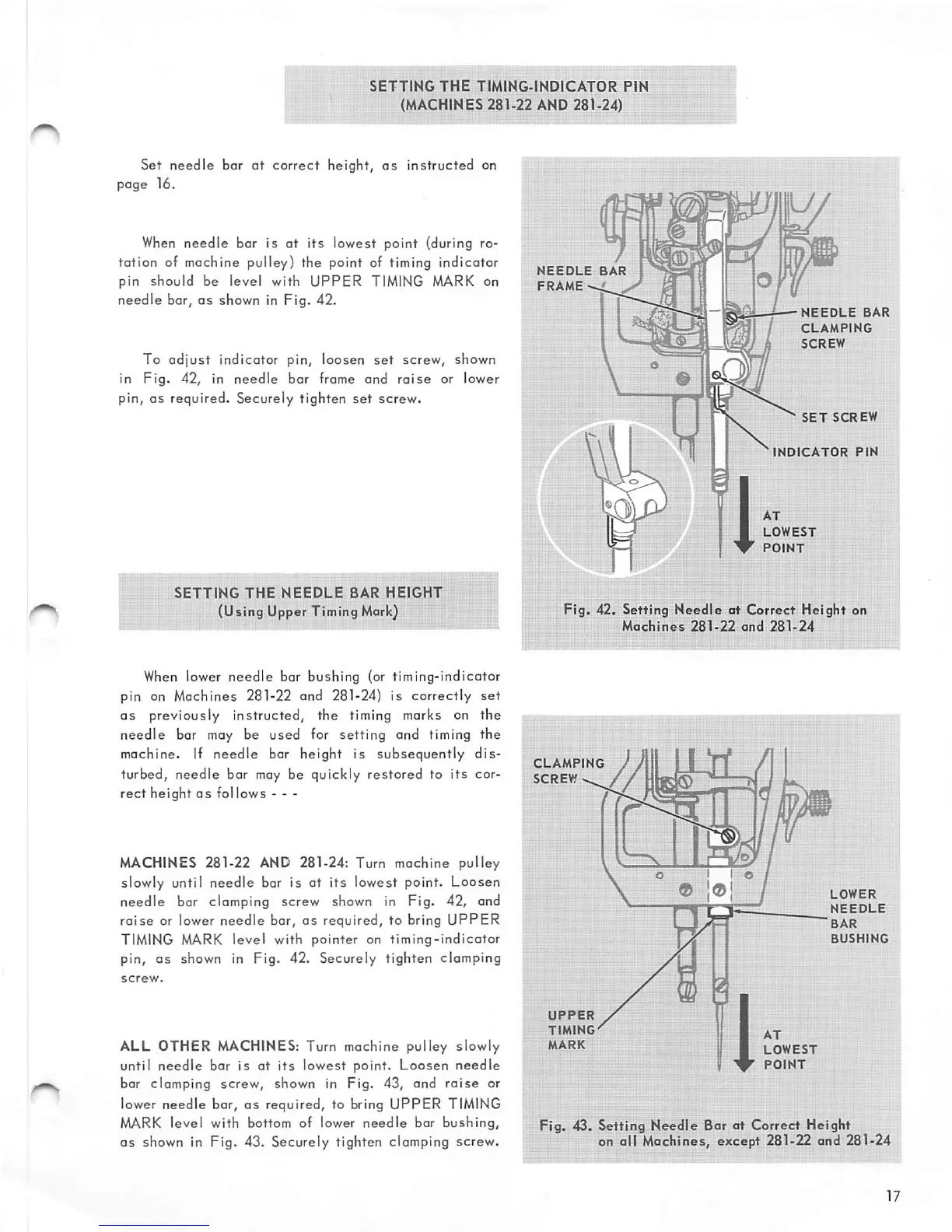
Set
needle
bar
at
correct
height,
as
instructed on
page
16.
When
needle
bar is at its lowest point {during ro
tation
of machine pulley) the point of timing indicator
pin
should
be level with
UPPER
TIMING MARK on
needle
bar,
as
shown in Fig. 42.
To
adjust
indicator pin, loosen
set
screw, shown
in
Fig.
42, in
needle
bar
frame
and
raise
or lower
pin, as required. Securely tighten
set
screw.
SETTING
THE
NEEDLE
8AR
HEIGHT
(Using Upper Timing
Mark)
When lower
needle
bar
bushing
(or
timing-indicator
pin on Machines 281-22 and 281-24) is
correctly
set
as
previously instructed, the timing marks on the
needle bar may be used for setting and timing the
machine. If
needle
bar height is subsequently
dis
turbed, needle bar may be quickly
restored
to
its
cor
rect
height
as
follows
- - -
MACHINES 281-22 AND 281-24: Turn machine pulley
slowly until
needle
bar is at
its
lowest point.
Loosen
needle
bar clomping screw shown in Fig. 42, and
raise
or lower
needle
bar,
as
required, to bring
UPPER
TIMING MARK
level
with
pointer
on
timing-indicator
pin, as shown in Fig. 42. Securely tighten clamping
ALL OTHER
MACHINES:
Turn machine pulley slowly
until
needle
bar is at
its
lowest
point.
Loosen
needle
bar clamping screw, shown in Fig. 43, and
raise
or
lower needle bar,
as
required, to bring UPPER TIMING
MARK
level
with bottom of lower
needle
bar
bushing,
as shown in Fig. 43. Securely tighten clamping screw.
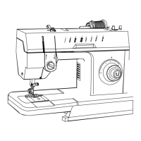
NEEDLE
BAR
FRAME--.'
^
NEEDLE
BAR
CLAMPING
SCREW
SET
SCREW
INDICATOR
PIN
AT
LOWEST
POINT
Fig. 42. Setting
Needle
at Correct Height on
Machines
281-22
and
281-24
CLAMPING
SCREW
^
UPPER
TIMING'
MARK
® 1®
AT
LOWEST
POINT
LOWER
NEEDLE
BAR
BUSHING
Fig.
43.
Setting
Needle
Bar at
Correct
Height
on all Machines, except 281-22 and 281-24