SETTING
THE
FEED
DOG HEIGHT
(Continued)
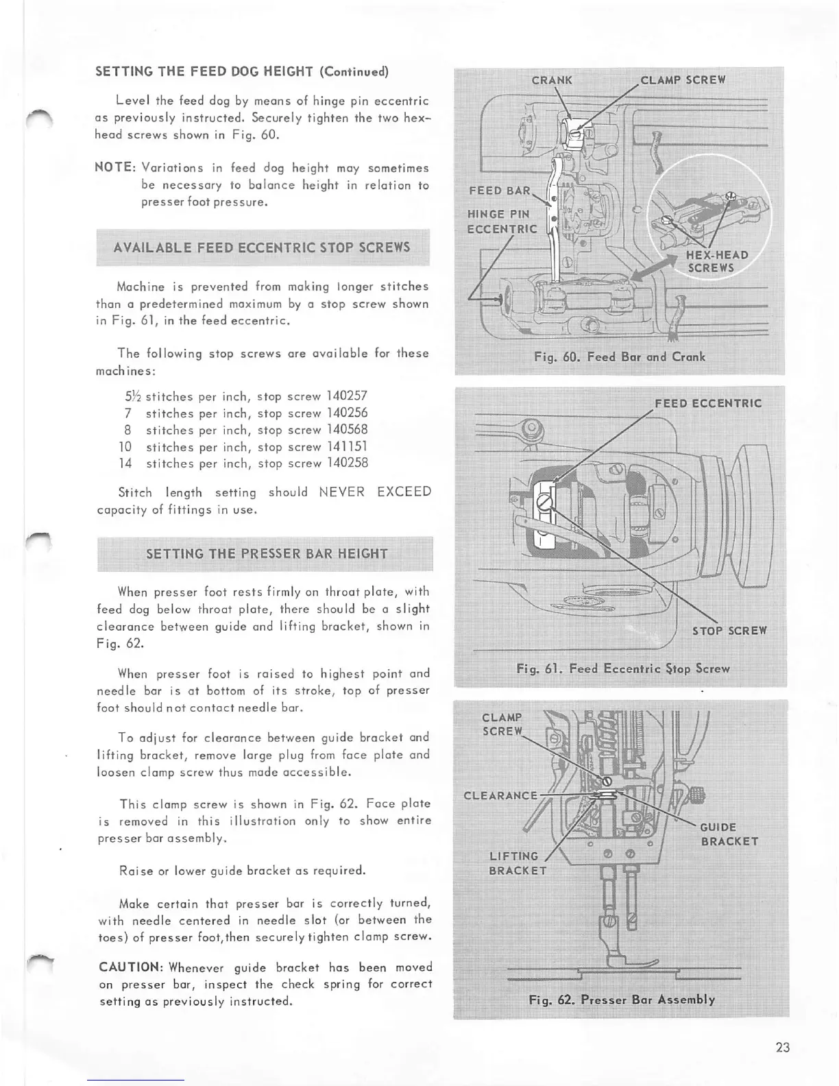
Level the feed dog by means of hinge pin
eccentric
as
previously instructed. Securely tighten the two
hex-
head screws shown in Fig. 60.
NOTE: Variations in feed dog height may sometimes
be
necessary
to
balance
height in relation to
presser
foot
pressure.
AVAILABLE
FEED
ECCENTRIC
STOP
SCREWS
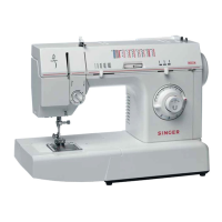
Machine is prevented from making longer
stitches
than a predetermined maximum by a stop screw shown
in
Fig.
61, in
the
feed
eccentric.
The following stop
screws
are
available
for
these
machines:
SYi
stitches
per inch, stop screw 140257
7
stitches
per inch, stop screw 140256
8
stitches
per inch, stop screw 140568
10
stitches
per inch, stop screw 141151
14
stitches
per inch, stop screw 140258
Stitch length setting should NEVER EXCEED
capacity
of
fittings
in
use.
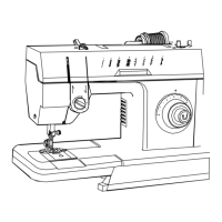
SETTING
THE
PRESSER
BAR
HEIGHT
i
When
presser foot
rests
firmly on throat plate, with
feed dog below throat plate, there should be a slight
clearance
between guide and lifting bracket, shown in
Fig. 62.
When
presser foot is raised to highest point and
needle
bor is at bottom of
its
stroke,
top
of
presser
foot
should
not
contact
needle
bar.
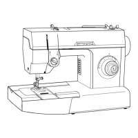
To adjust for clearance between guide bracket and
lifting bracket, remove large plug
from
face plate and
loosen clamp screw thus made
accessible.
This
clamp screw is shown in Fig. 62.
Foce
plate
is
removed in
this
illustration
only to show
entire
presser
bar
assembly.
Raise
or lower guide bracket
as
required.
Make
certain that presser bar is correctly turned,
with
needle
centered
in
needle
slot
(or
between
the
toes) of presser foot,then securely tighten clamp screw.
CAUTION: Whenever guide bracket has been moved
on
presser
bar,
inspect
the check spring for
correct
setting
as
previously instructed.
CRANK
FEED
BAR
HINGE
PIN
ECCENTRIC
-
CLAMP
SCREW
HEX-HEAD
SCREWS
Fig.
60.
Feed
Bar
and
Crank
FEED
ECCENTRIC
Fig. 61.
Feed
Eccentric
§top Screw
CLAMP
SCREW_
CLEARANCE
LIFTING
/
BRACKET
o e
GUIDE
BRACKET
Fig. 62.
Presser
Bar Assembly