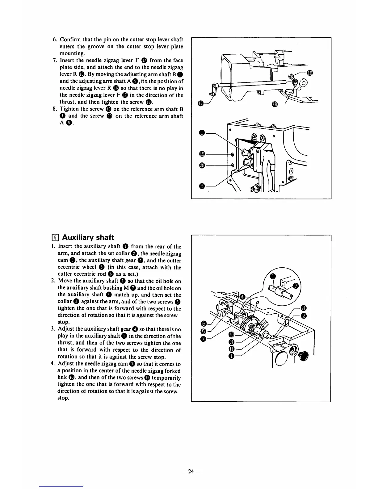
6.
Confirm
that
the
pin on the
cutter
stop
lever shaft
enters the groove on the
cutter
stop
lever plate
mounting.
7. Insert the needle zigzag lever F ® from the face
plate side,
and
attach
the end to the needle zigzag
lever R
®.
Bymovingthe adjusting arm shaft BO
and the adjustingarm shaft A
O,
fixthe position of
needle
zigzag
lever R 0 so that there is no playin
the needle zigzag lever F 0 in the direction of the
thrust,
and
then
tighten the screw
8. Tighten the screw 0 on the reference arm shaft B
O and the screw 0 on the reference
arm
shaft
A
0.
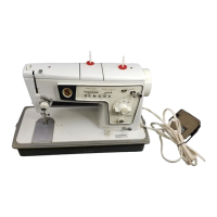
H] Auxiliary
shaft
1. Insert the auxiliary shaft O from the rear of the
arm, and attach the set collar0 , the
needle
zigzag
cam
0,
the auxiliary shaft gear
0,
and the cutter
eccentric wheel 0 (in this case, attach with the
cutter eccentric rod 0 as a set.)
2. Move the auxiliary shaft 0 so that the oil hole on
the auxiliary shaft bushing M0 and the oil hole on
the auxiliary shaft 0 match up, and then set the
collar0 againstthe arm, and ofthe two
screws
0
tighten the one that is forward with respect to the
direction of rotation so
that
it is against the screw
stop.
3. Adjust the auxiliary shaft gear 0 so that there is no
play in the auxiliary shaft 0 in the direction of the
thrust, and then of the two screws tighten the one
that
is forward with respect to the direction of
rotation so that it is against the screw stop.
4. Adjust the needle zigzag cam 0 so
that
it comes to
a position in the center of the needlezigzagforked
link
0,
and then of thetwo
screws
0 temporarily
tighten the one that is forward with respect to the
direction of rotation so
that
it isagainst the screw
stop.
0
-24-
0
0