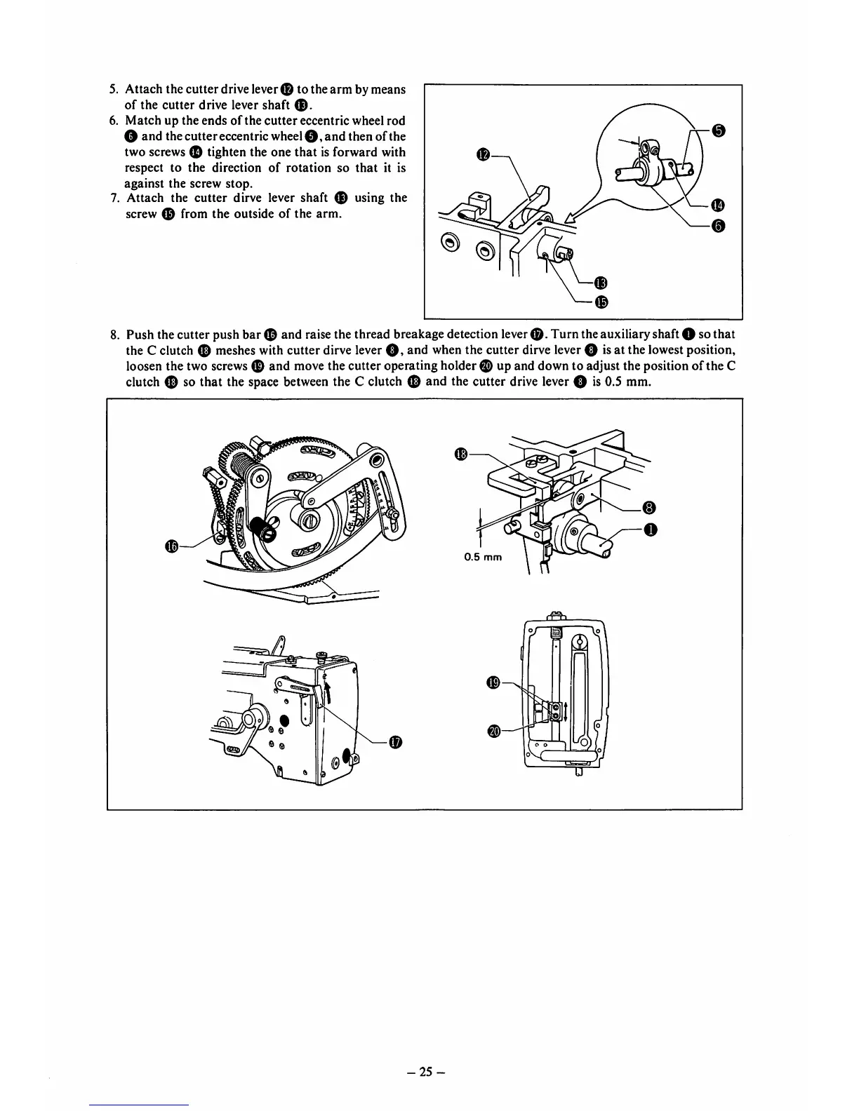
5. Attach the cutterdrive lever0 to the arm bymeans
of
the
cutter
drive
lever
shaft
6.
Match
up
the
ends
of
the
cutter
eccentric wheel
rod
O and the cuttereccentric wheel o ,
and
then of the
two screws 0 tighten the one that is forward with
respect to the direction
of
rotation
so
that
it is
against the screw
stop.
7.
Attach
the
cutter
dirve lever
shaft
using
the
screw 0 from the outside of the arm.
0
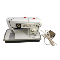
Push the cutter push bar 0 and raisethe thread breakagedetection lever
0.
Turn theauxiliaryshaftO sothat
the C clutch 0 meshes with cutter dirve lever
O,
and when the cutter dirve lever O isat the lowest position,
loosen the two screws 0 and move the cutter operating holder 0 up and down to adjust the position of the C
clutch 0 so that the space
between
the C clutch 0 and the cutter drive lever O is 0.5 mm.
-25