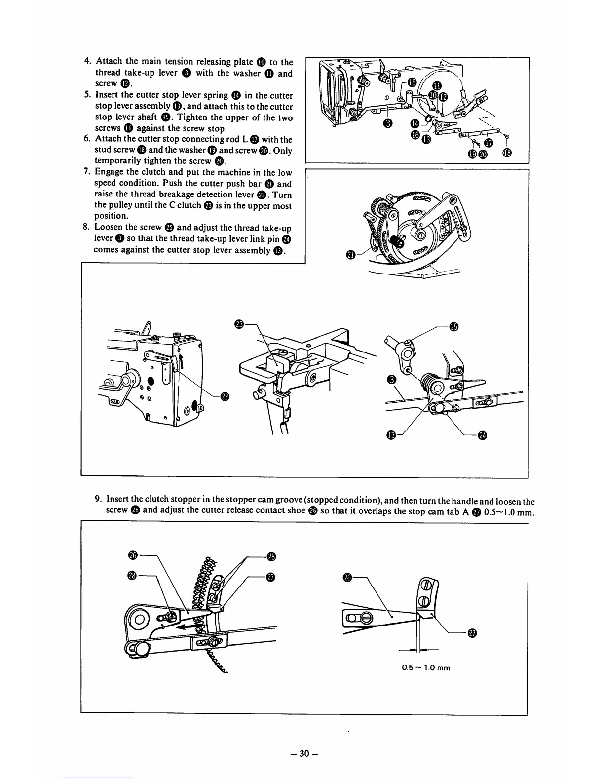
4. Attach the main tension releasing plate to the
thread take-up lever O with the washer O and
screw
0.
5. Insert the cutter stop lever spring in the cutter
stop leverassembly
0,
and attach this to the cutter
stop lever shaft Tighten the upper of the two
screws
0 against the
screw
stop.
6. Attach the cutter stop connecting rod L0 with the
stud
screw
0 andthe
washer
0 and
screw
0.
Only
temporarily tighten the screw
0.
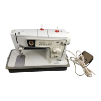
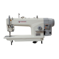
7. Engage the clutch and put the machine in the low
speed condition. Push the cutter push bar 0 and
raise the thread breakage detection lever
0.
Turn
the pulleyuntil the C clutch 0 isin the upper most
position.
8.
Loosen
the
screw
0 and adjustthethread
take-up
lever
0 sothatthe
thread
take-up
lever
link
pin
0
comes against the cutter stop lever assembly
0.
0
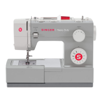
9. Insert the clutch stopper in the stoppercam groove (stopped condition), and then turn the handle and loosen the
screw
0
and
adjust
the
cutter
release
contact
shoe
0 so
that
it
overlaps
the
stop
cam
tab
A0
0.
5~1.0
mm.
0.5
~
1.0
mm
-30-