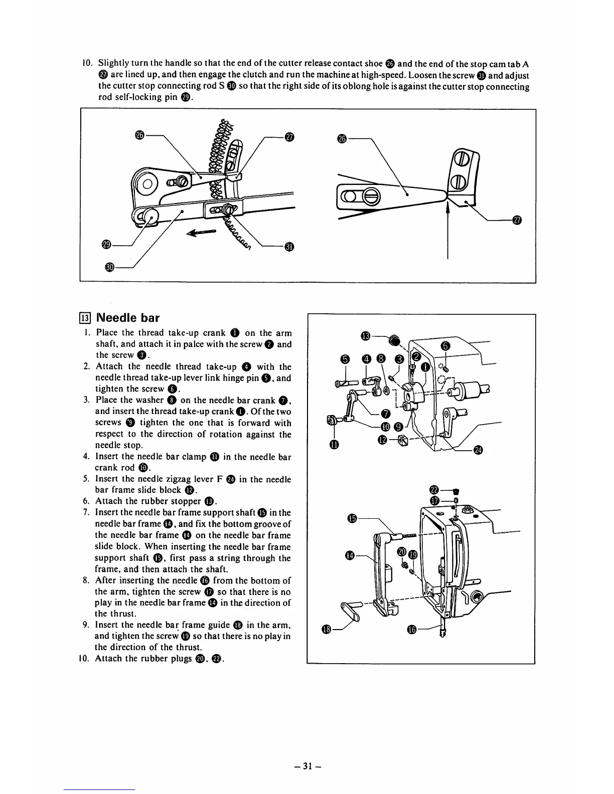
10.
Slightly turn the
handle
so that theendof the cutter
release
contactshoe© and theend ofthestop camtab A
® are
lined
up,and
then
engage
the
clutch
andrunthe
machine
at
high-speed.
Loosen
the
screw
0 and
adjust
thecutterstop
connecting
rodS 0 sothat the rightsideofits
oblong
hole
is
against
thecutterstop
connecting
rod self-locking pin
0.
m
0
0
[la]
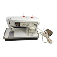
Needle
bar
1. Place the thread take-up crank O on the arm
shaft, and attach it in palce with the screw O and
the screw
0.
2. Attach the needle thread take-up O with the
needle thread take-up lever link hinge pin
0,
and
tighten the screw
0.
3. Place the washer 0 on the needle bar crank
0,
and insert the thread take-up crank
0.
Of the two
screws 0 tighten the one that is forward with
respect to the direction of rotation against the
needle
stop.
4. Insert the needle
bar
clamp 0 in the needle bar
crank
rod
5. Insert the needle zigzag lever F 0 in the needle
bar
frame
slide
block
6. Attach the rubber stopper
0.
7. Insert the needle
bar
frame support shaft 0 in the
needlebar frame 0 , and fix the bottom grooveof
the needle
bar
frame 0 on the needle
bar
frame
slide block. When inserting the needle bar frame
support shaft
0,
first pass a string through the
frame,
and
then
attach
the
shaft.
8. After inserting the needle 0 from the
bottom
of
the arm, tighten the screw 0 so that there is no
play in the needle
bar
frame 0 in
the
direction
of
the
thrust.
9. Insert the needle
bar
frame guide 0 in the arm,
and tighten the screw0 so that there is no playin
the
direction
of
the
thrust.
10. Attach the rubber plugs
0,
0.
31
-
0 0 0 0
(swL
0—®
0