SiMUaA
®
Sew
Reach
P10
Introduction
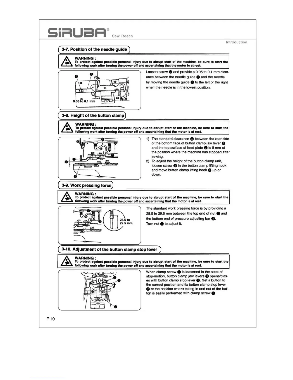
( 3-7. PosHlon
of
the needle guide)
Loosen screw e and provide a 0.
05
to 0.1
mm
clear-
an
ce
between the needle guide e
and
the needle
by moving the
need
le guide e to the left
or
the right
when the needle
is
in the lowest position.
(
3-8
. Height of
the
button clamp)
•
WARNING :
To
proe.ct
against
poulble
personal I
njury
due
to
a
brupt
s
ta
rt
ol
the
machine,
be
sure
to
s
tart
the
following
work
after
turning
the
power
off
and
ascertaining
that
the
motor
Is
at
rest.
1) T
he
standard clearan
ce
e
be
tw
een the rear si
de
of the
bo
ttom
f
ace
of button clamp
jaw
lever 8
and the t
op
surface
of
feed plate •
is
8 mm
at
the position where the machine has stopped after
sewing.
2)
To adjust the
he
i
ght
of
the button clamp unit,
loosen screw
•
in
t
he
bu
tt
on
clamp lifting hook
and move button clamp lifting hook
8 up or
do
wn.
( 3-9. Work pressing force)
WARNING
:
To pro18ct against
poNlble
per90nal I
njury
due
to
abrupt
start
of
the
mach
i
ne
,
be
sure
to
start
th
e
followlng work
after
turning
the
power
off
and
ascertaining
that
the
motor
Is
at
rest.
~®-
510
~
29
.
5mm
l1'!i
& e
ar=
~
The
standard work pressing for
ce
is by providing a
28
.5
to
29
.5
mm
between the
to
p
en
d
of
nu
t e and
the bottom end
of
pressure a
dj
usting
bar
• ·
Turn nut
e
to
adju
st
it.
( 3-10. Adjustment
of
the button clamp stop lever )
WARNING:
To
proe.ct
against
poNlble
penona1
Injury
due
to
a
brupt
start
of
the
machine
,
be
su
re
to
start
the
following
work
after
turning
the
power
off
and
asc«talnlng
that
the
motor
fa
at
mt
.
When
clamp
scre
w e
is
loosen
ed
in
the state
of
stop-motion, button clamp
ja
w levers e opens/clos-
es
with button cl
amp
stop
lev
er e.
Set
a
bu
tt
on
to
the correct
posi
tion and
fix
button clamp
sto
p l
ever
e at t
he
posi11on
where taking
in
an
d
out
of
the
but-
ton
is
easily performed with clamp screw • ·