SiMUaA
®
Sew
Reach
Introduction
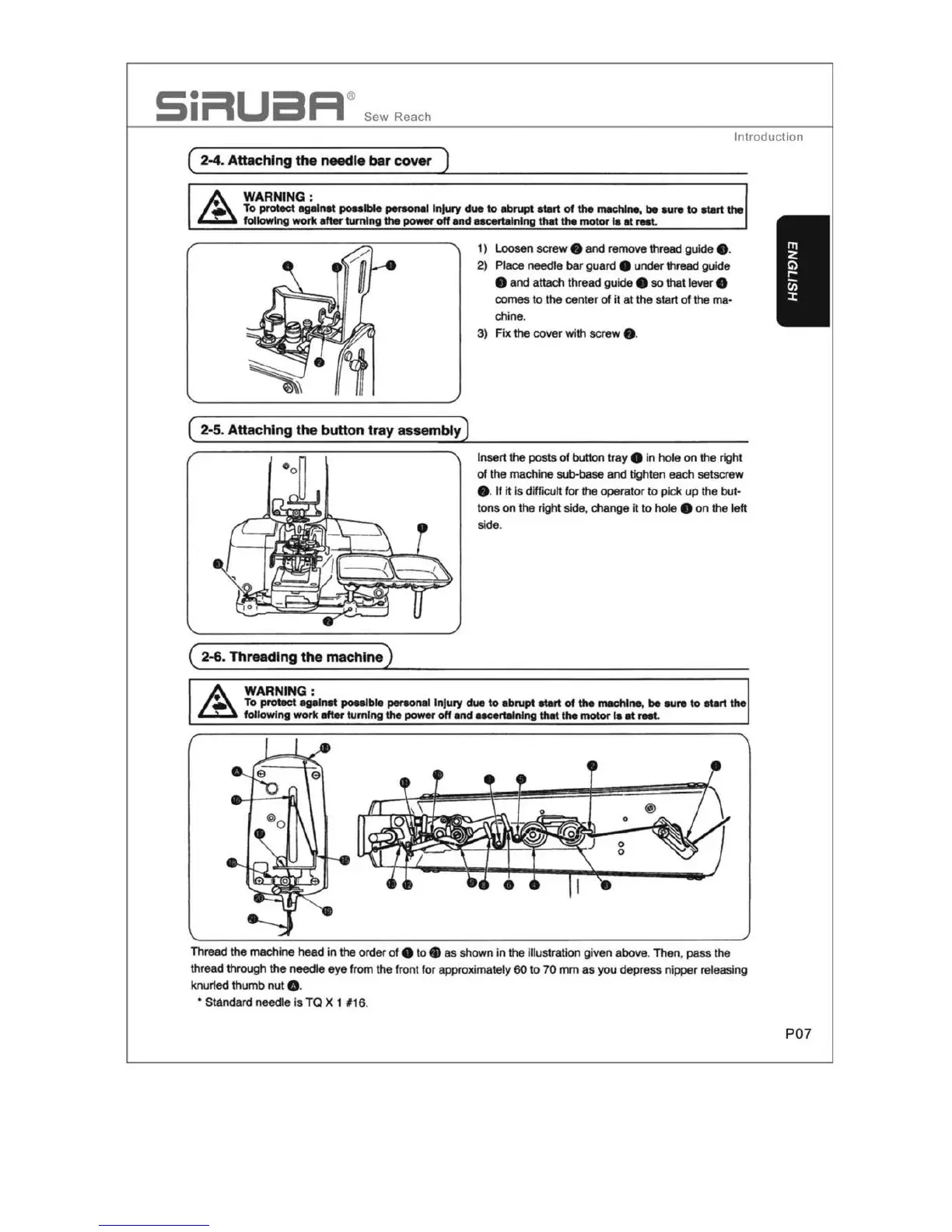
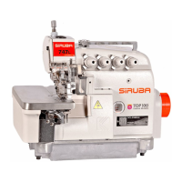
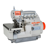
( 2-4. Attaching
the
needle
bar
cover )
WARNING
:
To protect against
poalble
peraonal lnJu,y
due
to
abrupt
atart
of
the
machine,
be
aure to atart
the
followlng
work
an.
turning
the
poww
off
and
aacertalnlng
that
the
motor
la
at
rNt.
( 2-5. Attaching the button tray assembly)
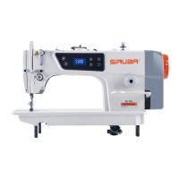
( 2-6. Threading the
machine)
WARNING
:
1) Loosen
screw
9 and remove thread guide e.
2)
Place needle
bar
guard 9 under
thread
guide
9
and
attach thread guide 9 so that lever 8
comes to the center
of
it
at
the start
of
the ma•
chine.
3)
Fix
the cover with screw • ·
Insert
the
posts
of
button
tray
e In
hole
on
the right
of
the
machine sub-base
and
tighten each setscrew
e. If it is difficult for the operator
to
pick
up
the
but·
tons
on
the right side, change
it
to
hole
e
on
the left
side.
To protect agalnat
poalbi.
per90nal
Injury
due
to
abrupt
start
of
the
machine,
be
aure
to
atart
the
fol
lowlng
work
after
tumlng
the
po-
off
and
aacertalnlng
that
the
motor
la
at
l'Nt.
Thread
the
machi
ne
head
in
the order of e
to•
as
shown
in
the
Illustration given above. Then, pass the
thread through
the
needle eye from the front
for
approximately
60
to
70
mm
as
you
dep
r
ess
nipper rel
eas
i
ng
knur1ed thumb
nut
e.
• Standard needle
is
TO
X 1 #16.
P07