INSTALLATION AND OPERATING INSTRUCTIONS
SKF Multilog On-line System IMx-8/IMx-8Plus
SKF Multilog On-line System IMx-8/IMx-8Plus
User Manual
Revision E
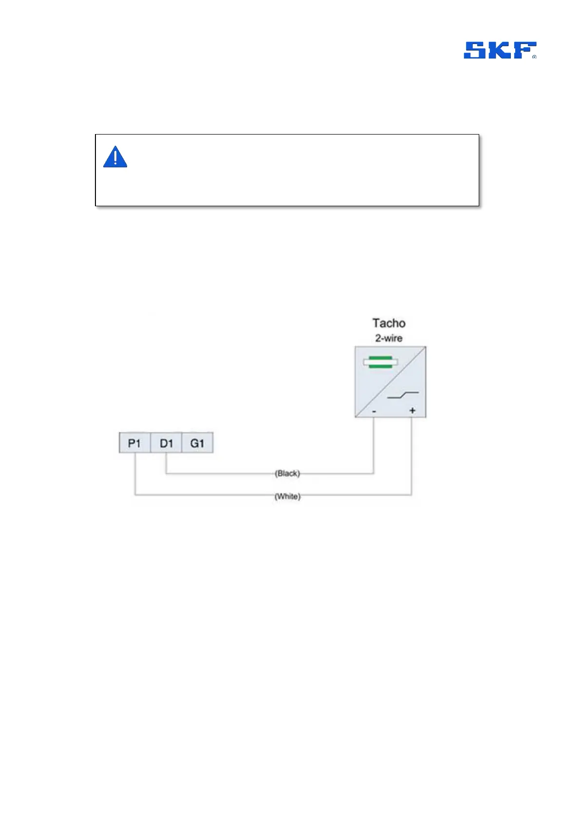
By design, the IMx-8/IMx-8Plus supply power to both digital input channels, on
terminals P1 and P2.
The sensor can be connected to the relevant digital input terminals as illustrated in
the following diagrams, Figure 13 to Figure 15. Connect appropriately to the type of
sensor being used.
Note that the different sensor types illustrated in these figures, are supported by all
digital input channels; the channel shown in any particular figure is only an example.
Figure 13 IMx powered, 2-wire sensor connected to digital input 1
Sensor power at P1 and P2 is always enabled and cannot be controlled or
configured by hardware or software. Trigger level and hysteresis are also fixed,
refer specifications, 3.2.4.