Page 27 of 56
SKIPPER Electronics AS
Edition: 2021-09-16
ESN100 Operation and Installation Manual
Chapter: System Setup
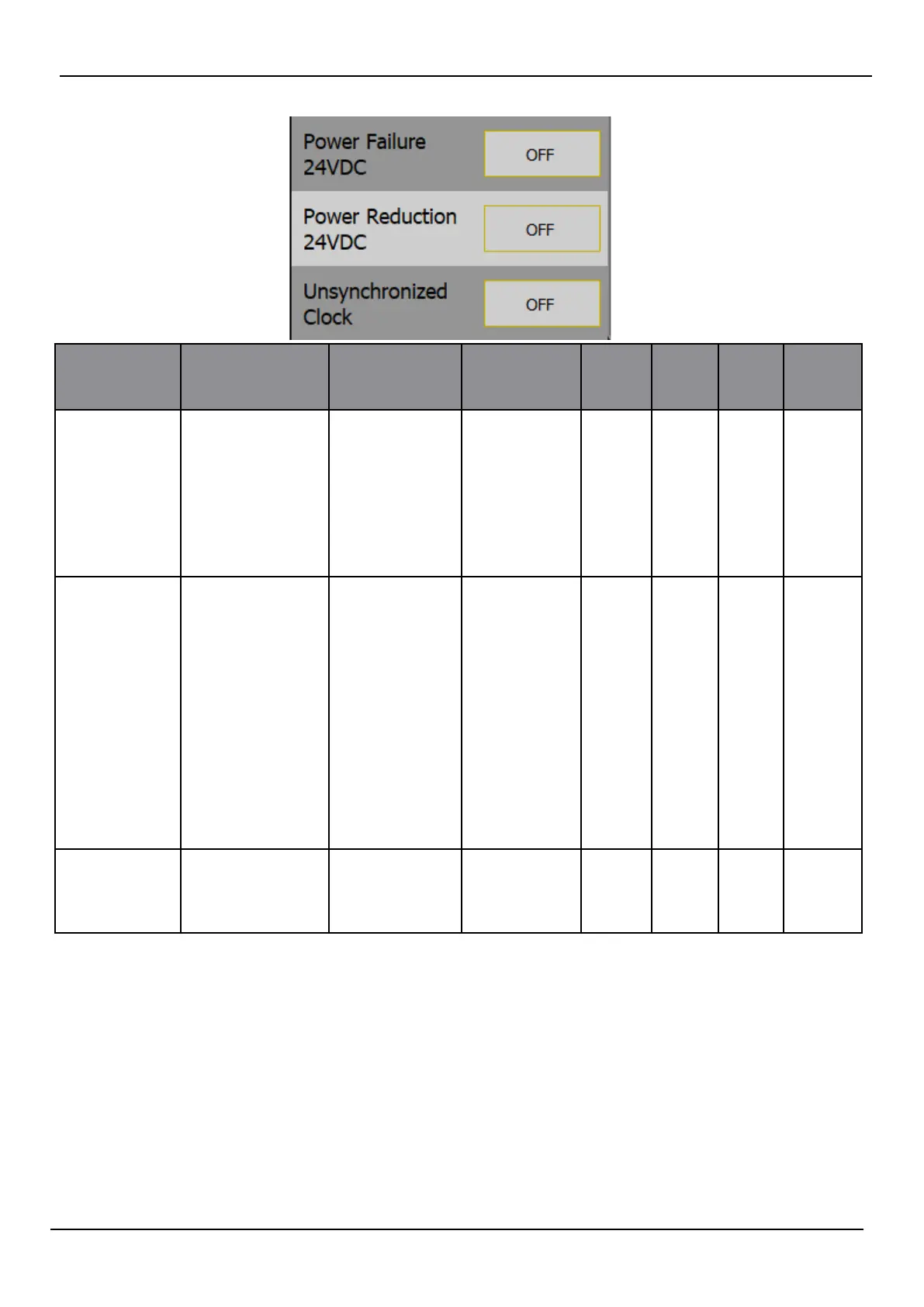
Alert title Alert
message
Message
Description
Alert types
selectable
default Alert
ID
ALF
Alert
ID
ALR
Remote
Ack
Power failure
24VDC
POWER FAIL DISPLAY 24V
<12V
TRANS-
CEIVER 24V
< 12V
VOLTAGE
TOO LOW
<12V
• Warning
• O
O 3022 460 Yes
Power
reduction
24VDC
POWER
REDUCTION
DISPLAY 24V
< 21V
DISPLAY 24V
>30V
TRANS-
CEIVER 24V
<21V
TRANS-
CEIVER 24V
>30V
ALL 24V<21V
ALL 24V>30V
• Warning
• O
O 3022 460 Yes
Unsynchro-
nised clock
UNSYNCH
CLOCK
NO EXTER-
NAL CLOCK
INPUT
• Caution
• O
O 3119 119 No
Extra comments:
A number of alerts will provide a second sentence with some diagnostic help, stating which part of
the system has the error and what the probable cause is.
Internal errors are caused by the settings on the system
System failure means the system is not working to specication
Escalation
Escalation is the process of reminding the bridge sta that a warning has not been handled. The
user can set a time that the system will wait before reminding. Escalation
can either be sending
a new message of the same status (warning) or can change the warning to an alarm, thereby
demanding attention.