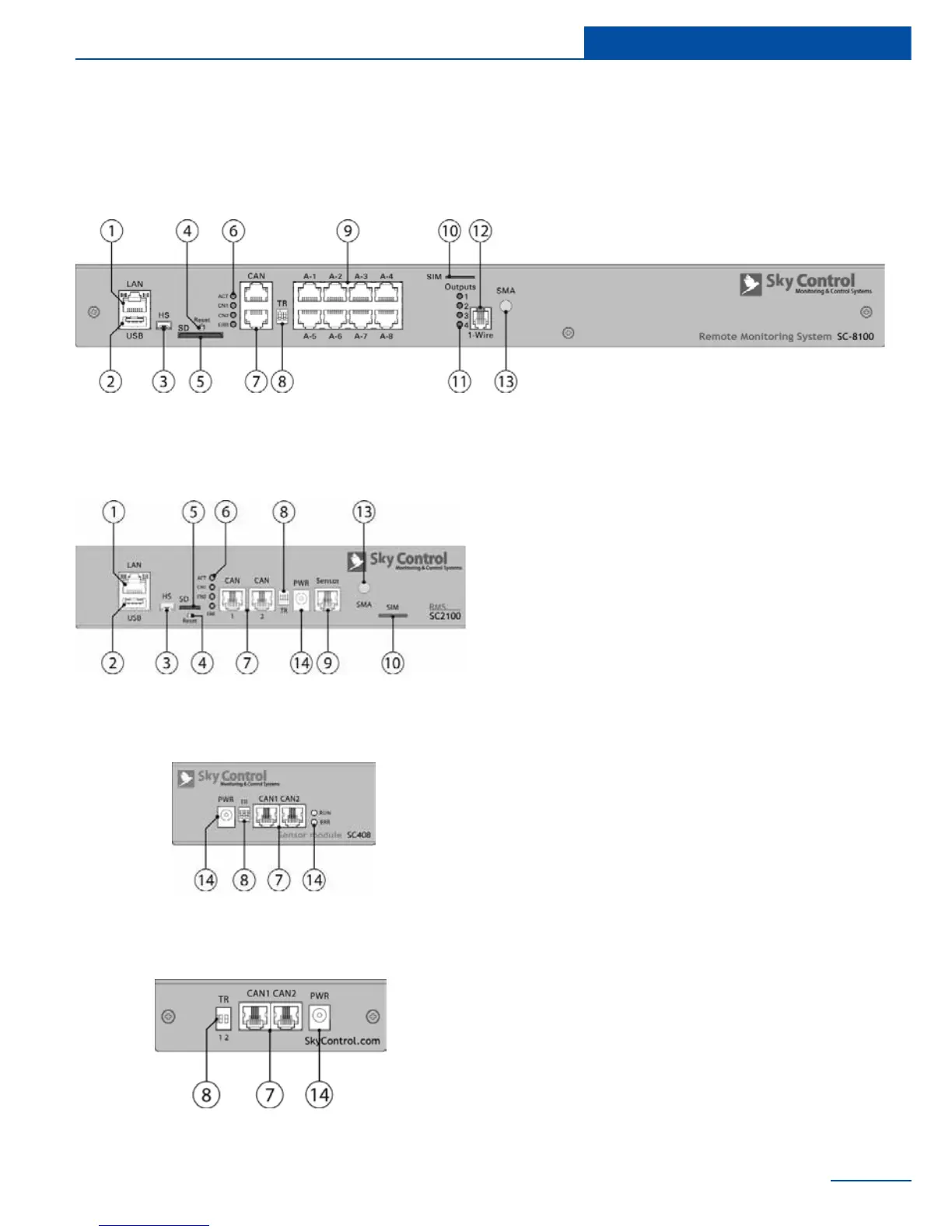
Physical description
1 “LAN” - Ethernet 10/100 Base-T port,
provides Ethernet connection.
• LEDs - “yellow” (status) and “green”
(trafc) shows the network trafc.
The status LED: ashes green when
system starts up, shows the connec-
tion state (constant green light - the
connection is established, blinking
green - the connection attempt).
2 “USB” - type A USB-port 2.0, is required
for USB ash drive to upgrade an appli-
ance.
3 “HS” - type miniAB USB-port 2.0, required
to connect a USB camera or to restore an
appliance.
4 “Reset” - resets the appliance.
5 “SD” - SD card connector with ejector,
needed to store data.
6 LEDs: “ACT” - indicates appliance status,
“CN1” - indicates CAN1 bus trafc, “CN2”
- indicates CAN2 bus trafc, “ERR»” -
indicates error and trafc.
7 “CAN” - two equivalent digital connectors
RJ12 for the connection of CAN sensors
and CAN extensions on a CAN bus, with
auto-sensing.
8 “TR” - CAN terminator, required for a con-