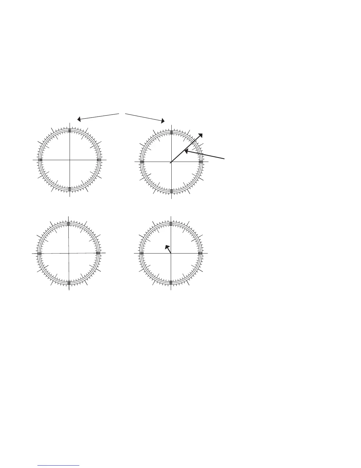
Explanaon of the Figures
A: Following tripod and/or wedge
adjustments SAM has been aimed so that
the distant target (X) falls under the central
cross of the recule paern.
ACTION: Now Rotate the Polar Scope 180
degrees.
B: Aer rotaon the target appears displaced
due to misalignment of the polar scope
recule.
ACTION: Adjust the recule using the three
Allen screws (see page 38) unl 1/2 of the
error has been corrected.
C: Using the tripod and/or wedge
adjustments re-centre the target under the
cross hair.
ACTION: Rotate the Polar Scope 180 degrees
(back to the original starng posion).
D: Note any deviaon of the target. If any
signicant deviaon remains repeat the
steps starng at A.
9
3
6
NCP
SCP
A
B
C
D
X
X
X
X
Adjust recule unl
target appears here
These gures represent the view through the polar scope when a target
is inially centered (A), aer Polar Scope has been rotated 180 degrees
(B), aer the recule adjustment has been made and SAM has been re-
centered on the target (C), and the target displacement aer the second
180 degree rotaon. There is a bit of displacement le as shown here,
but one more iteraon of the recule alignment is likely all that would be
needed to remove it.
Note how the orientaon of the recule changes when
Polar Scope is rotated 180 degrees.
37
 Loading...