SECTION 5, Page 16 SJ-800 Series E Battery Powered
119153
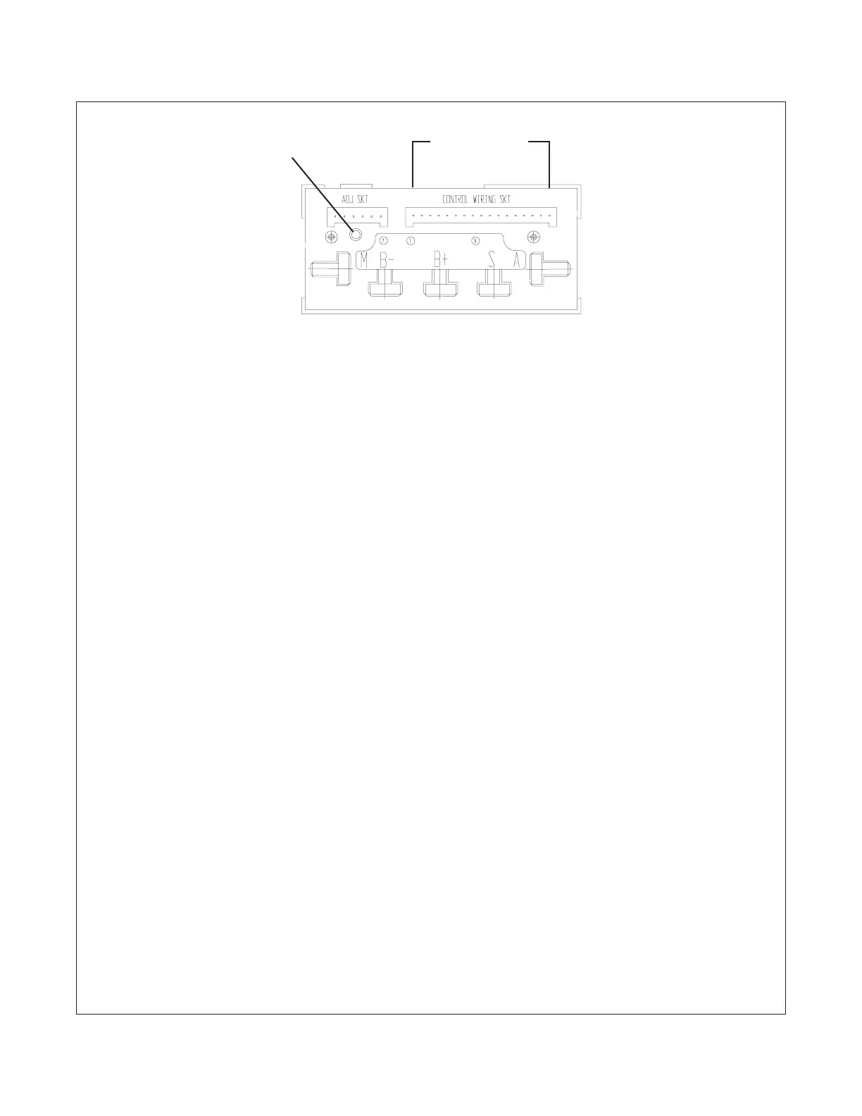
Traction Controller Pin Reference
Figure 5-7. Traction Controller
Pins are identified from left to right
Pin #1 thru Pin #17
Diagnostic LED
Sevcontroller Adjustment And Diagnostics (Continued)
Pin 1- Brake relay control.
Brings B- to brake relay (25CR).
Test between pin 1 and wire #10A.
Pin 2- Direction signal from pin 4 of tachometer
card. Determines direction.
0 volts = forward.
15 volts = reverse.
Test between pin 4 and wire #02.
Pin 3- Not used.
Pin 4- High Drive Cut-out.
24 volts high drive enabled.
0 volts high drive disabled.
Test between pin 4 and wire #02 with plat-
form fully lowered.
Pin 5- 24 volt input from line contactor.
Test between pin 6 and wire #02.
Pin 6- 48 volt input from line contactor.
Test between Pin 6 and wire #02 with Key
Switch on.
Pin 7- Tilt switch input.
24 volts = full speed
0 volts = 50% full speed.
Test between pin 7 and wire #02.
Pin 8- Forward/Up input from joystick.
24 volts = drive forward or lift up selected.
Test between pin 8 and wire #02.
Pin 9- Not used
Pin 10- Not used
Pin 11- Reverse direction input from joystick
24 volts = reverse selected.
Test between pin 11 and wire #02.
Pin 12- Speed signal from pin 2 on tachometer
card.
7.5 volts with joystick in neutral.
7.5 volts to 15 volts = reverse.
7.5 volts to 0 volts = forward.
Test between pin 12 and wire #02.
Pin 13- Speed sensing enable.
Determines lift or drive mode.
2 volts = drive. Speed sensing enabled.
4 volts = lift. Speed sensing disabled.
Anything above 2.52 volts = Lift
Test between pin 13 and wire #02.
Pin 14- Accelerator input.
3.8 to 4.2 volts with joystick in neutral and
key switch on.
3.5 volts = slow speed.
0 volts = fast speed.
Test between pin 14 and wire #02.
Pin 15- Forward contactor output.
Brings B- to forward drive contactor.
Test between pin 15 and wire #10A.
Pin 16- Drive/Lift Select.
0 volts = drive
24 volts = lift
Test between pin 16 and wire #02.
Pin 17- Reverse contactor output.
Brings B- to reverse drive contactor.
Test between pin 17 and wire #10A.
 Loading...


