14
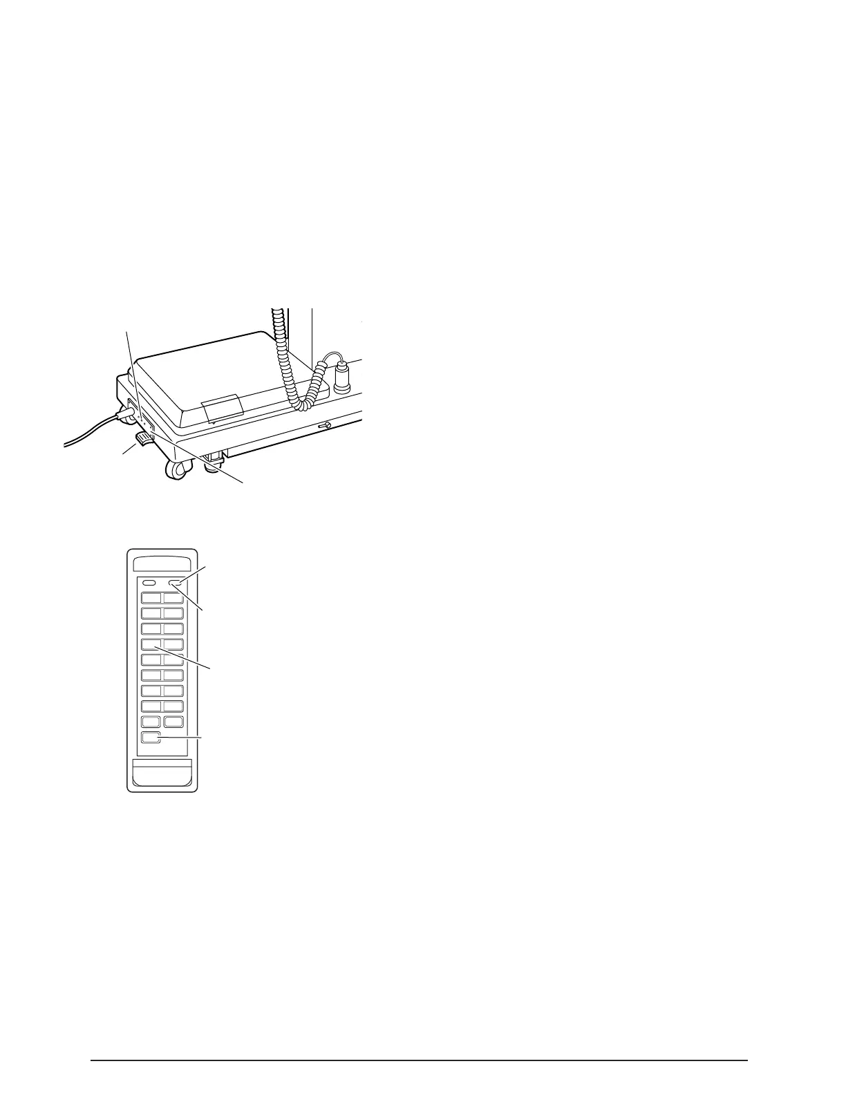
BATTERY CHARGING
INDICATOR LIGHT
ELECTRICAL
ENCLOSURE
MAIN
POWER
SWITCH
3-1. Battery Model Table, AC 120V Operation
a. Be sure the power cord is plugged into a
properly grounded, Hospital Grade, 120VAC out-
let. Make sure the power cord is routed to the outlet
to prevent it from being in the way of operating
personnel.
b. Depress the main power ON/OFF switch
located on the electrical enclosure. See figure 3-1.
The green AC 120V, Power-On indicator light lo-
cated in the upper right corner of the pendant
control will illuminate. See figure 3-2.
SECTION III BATTERY MODEL OPERATION
c. The table is now ready for 120VAC operation.
Press the TABLE UP button on the pendant control
to set the table’s brakes. An electronic timer will
activate the brake system until the brakes are
completely set, approximately 8-10 seconds. Press
the desired function button to position the table.
NOTE
•If brakes fail to set, make sure the
Emergency Brake Release Lever is
tight (clockwise).
•If the Emergency Brake Release Valve
has been operated, the BRAKE UN-
LOCK button on the pendant control will
have to be pressed before brakes will
lock again.
NOTE
•Turning the Main Power Switch ON will
change the table operation to 120 VAC
power regardless of the position of the
BATT button.
•If Battery operation is activated while
Main Power Switch is ON there will be
approximately a 4 second delay before
Battery operation activates.
3-2. Battery Operation
a. Make sure the green, AC 120V, Power-On
indicator light, on the hand-held pendant control, is
OFF. See figure 2-2. If the indicator light is ON,
depress the main power ON/OFF switch, located
on the electrical enclosure to turn AC120V opera-
tion OFF.
NOTE
The power cord may be removed from
the table. The table will operate cor-
rectly on battery power with the power
cord connected to a wall outlet or dis-
connected.
b. Press the BATT button on the hand-held
pendant control. The red BATTERY indicator light,
located in the upper right corner of the pendant
control, will illuminate. This confirms that the table
is now being operated with battery power.
c. The table is now ready to operate on battery
power. Press TABLE UP button on the pendant
control to set the table’s brakes. An electronic timer
will activate the brake system until the brakes are
completely set, approximately 8-10 seconds. Press
desired function button to position the table.
d. To extend the battery charge life, turn the
BATTERY power OFF with the pendant control
when the table is not going to be used.
NOTE
Battery Operation must be turned OFF
at the pendant control. It can not be
turned Off using the main power switch.
Figure 3-2. Pendant Control
Figure 3-1. Main Power Switch
ELITE/
3500B
CAUTION
HANG PENDANT CONTROL
ON SIDE RAIL WHEN NOT IN
USE. KEEP CORD CLEAR OF
MOVING PARTS.
REV.
TREND
TREND
TILT
LEFT
TILT
RIGHT
BACK
UP
BACK
DOWN
TABLE
UP
TABLE
DOWN
SLIDE
HEAD
SLIDE
FOOT
LEG
UP
LEG
DOWN
FLEX REFLEX
KIDNEY
UP
KIDNEY
DOWN
RETURN
BRAKE
UNLOCK
RETURN/CTR POWER BATT
BATT
*
PRESS TO
LOCK BRAKES
*
AC120V POWER ON
INDICATOR LIGHT
(GREEN)
BATTERY ON/OFF
SELECTOR BUTTON
BATTERY POWER
INDICATOR LIGHT
(RED)
TABLE UP
(BRAKE LOCK)

 Loading...


