19
ELITE/
3500B
CAUTION
HANG PENDANT CONTROL
ON SIDE RAIL WHEN NOT IN
USE. KEEP CORD CLEAR OF
MOVING PARTS.
REV.
TREND
TREND
TILT
LEFT
TILT
RIGHT
BACK
UP
BACK
DOWN
TABLE
UP
TABLE
DOWN
SLIDE
HEAD
SLIDE
FOOT
LEG
UP
LEG
DOWN
FLEX REFLEX
KIDNEY
UP
KIDNEY
DOWN
RETURN
BRAKE
UNLOCK
RETURN/CTR POWER BATT
BATT
*
PRESS TO
LOCK BRAKES
*
KIDNEY
UP
KIDNEY
DOWN
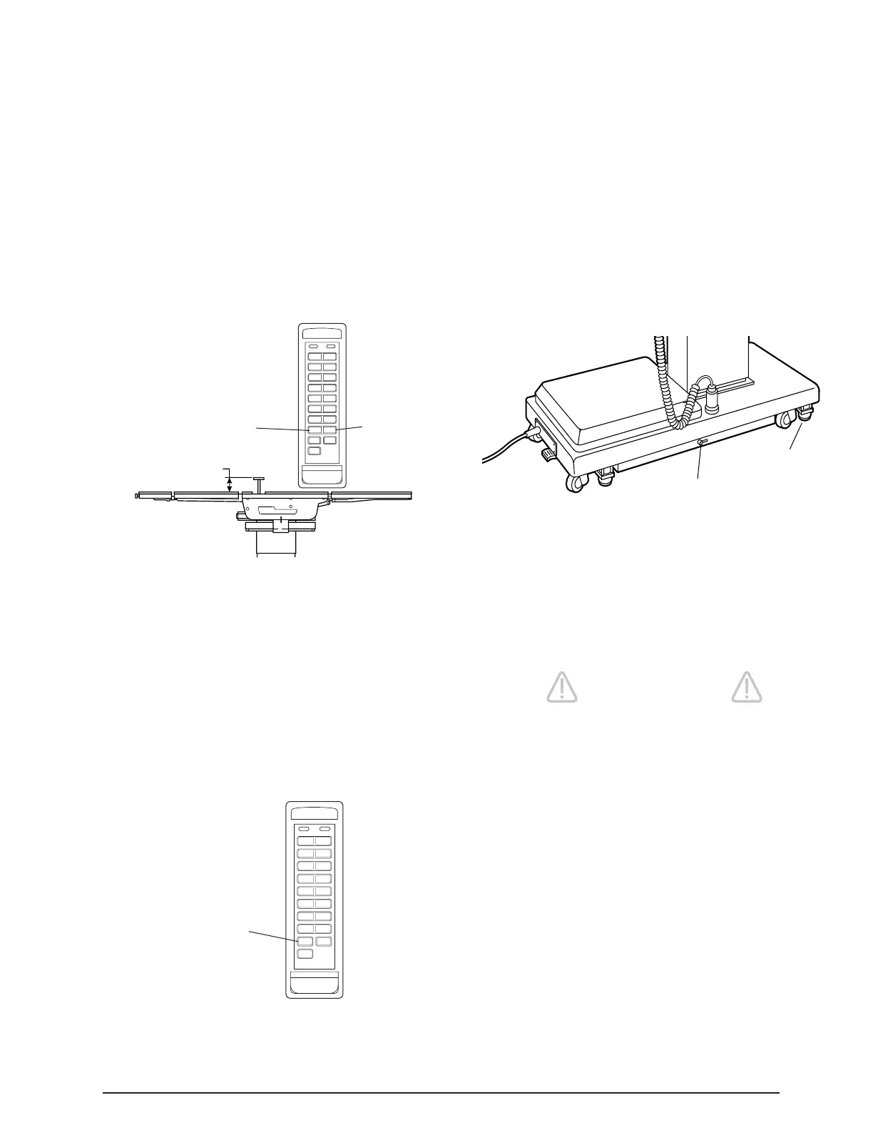
5-1/2"
i. Kidney Lift. To raise the built-in kidney lift,
press the KIDNEY-UP button (figure 3-14). Up to
5-1/2 inches of lift can be achieved. Press the
KIDNEY -DOWN button to lower the kidney lift.
NOTE
To prevent damage to the kidney lift, a
safety interlock prevents the kidney lift
from going up if the back section is 45°
above horizontal.
j. Return To Level. To return the table top to a
level position, press the RETURN button (figure 3-
15).
NOTE
Elevation, kidney lift, top slide and brake
system functions are not affected by
the return to level function.
Figure 3-14. Kidney Lift Positioning
Figure 3-15.
ELITE/
3500B
CAUTION
HANG PENDANT CONTROL
ON SIDE RAIL WHEN NOT IN
USE. KEEP CORD CLEAR OF
MOVING PARTS.
REV.
TREND
TREND
TILT
LEFT
TILT
RIGHT
BACK
UP
BACK
DOWN
TABLE
UP
TABLE
DOWN
SLIDE
HEAD
SLIDE
FOOT
LEG
UP
LEG
DOWN
FLEX REFLEX
KIDNEY
UP
KIDNEY
DOWN
RETURN
BRAKE
UNLOCK
RETURN/CTR POWER BATT
BATT
*
PRESS TO
LOCK BRAKES
*
RETURN
TO LEVEL
3-7. Emergency Brake Release.
In case of a power failure or an electrical problem
within the table, the emergency brake release
system can be used to move the table. The control
lever for this function is located on the side of the
table base and is identified by an EMERGENCY
BRAKE RELEASE label. Turn the lever counter-
clockwise to release the brakes. See figure 3-16.
EMERGENCY
BRAKE RELEASE
BRAKE (4)
Figure 3-16. Emergency Brake Release
CAUTION
•The Emergency Release Valve must
be closed and tightened (clockwise)
before activating any hydraulic func-
tion.
•If the Emergency Brake Release Valve
has been operated, the UNLOCK but-
ton on the pendant control will have to
be pressed before brakes will lock
again.

 Loading...


