7
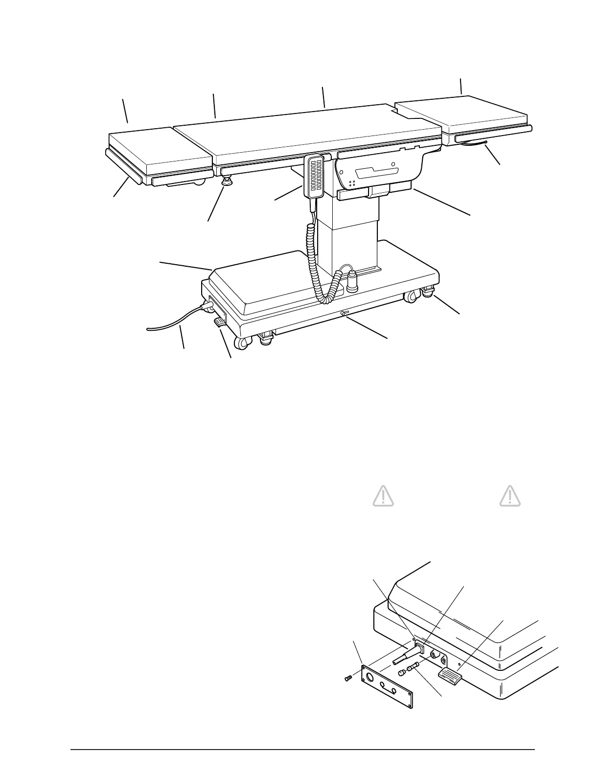
HEAD
SECTION
BACK
SECTION
SEAT
SECTION
REMOVABLE
LEG SECTION
LEG SECTION
RELEASE
LEVER
TOP SLIDE
CYLINDER
FLOOR/LOCK
BRAKE (4)
EMERGENCY
BRAKE RELEASE
MAIN
POWER
SWITCH
POWER CORD
SERVICE
ACCESS
COVER
HEAD SECTION
LOCKING KNOB
PENDANT
CONTROL
SIDE
RAIL
SECTION I INTRODUCTION
Figure 1-2. Power Switch and Fuse Location
1-1. General
SKYTRON’s Elite 3500 Series Surgical Tables are
electro-hydraulically operated, general purpose sur-
gical tables. See figure 1-1.
The electro-hydraulic positioning functions oper-
ated by the hand-held, push button, pendant control
unit are: trendelenburg, lateral tilt, back section,
elevation, leg section, top slide, flex/reflex, kidney
lift, return to level, and the floor lock/brake system.
Manual controls are provided for head section posi-
tioning, emergency brake release and leg section
removal.
1-2. Power Requirements
The Elite 3500 Surgical Table requires a 120VAC,
60 Hz electrical power supply. The table is equipped
with a 15 foot long power cord with a standard three
prong, hospital grade plug. The electrical protection
fuses (2) are located behind a cover plate in the
electrical enclosure on the front edge of the base.
See figure 1-2. The main power ON/OFF switch is
located on the electrical enclosure.
WARNING
Risk of electrical shock. Make sure
power cord is disconnected prior to
accessing fuses.
Figure 1-1. Elite 3500
(2) FUSES
10 AMP FA
MAIN POWER
SWITCH
POWER
CORD
ELECTRICAL
ENCLOSURE
COVER
PLATE

 Loading...


